PCIe riser cable routing
Use the section to understand the cable routing for the PCIe risers.
Note
- Connections between connectors; 1↔1, 2↔2, 3↔3, ... n↔n
- When routing the cables, ensure that all cables are routed appropriately through the cable guides.
- A label on each cable indicates the connection source and destination. This information is in the format RY-X and P Z. Where Y indicates the PCIe riser number, X indicates the connector on the riser card, and Z indicates the connector on the system board assembly.
Attention
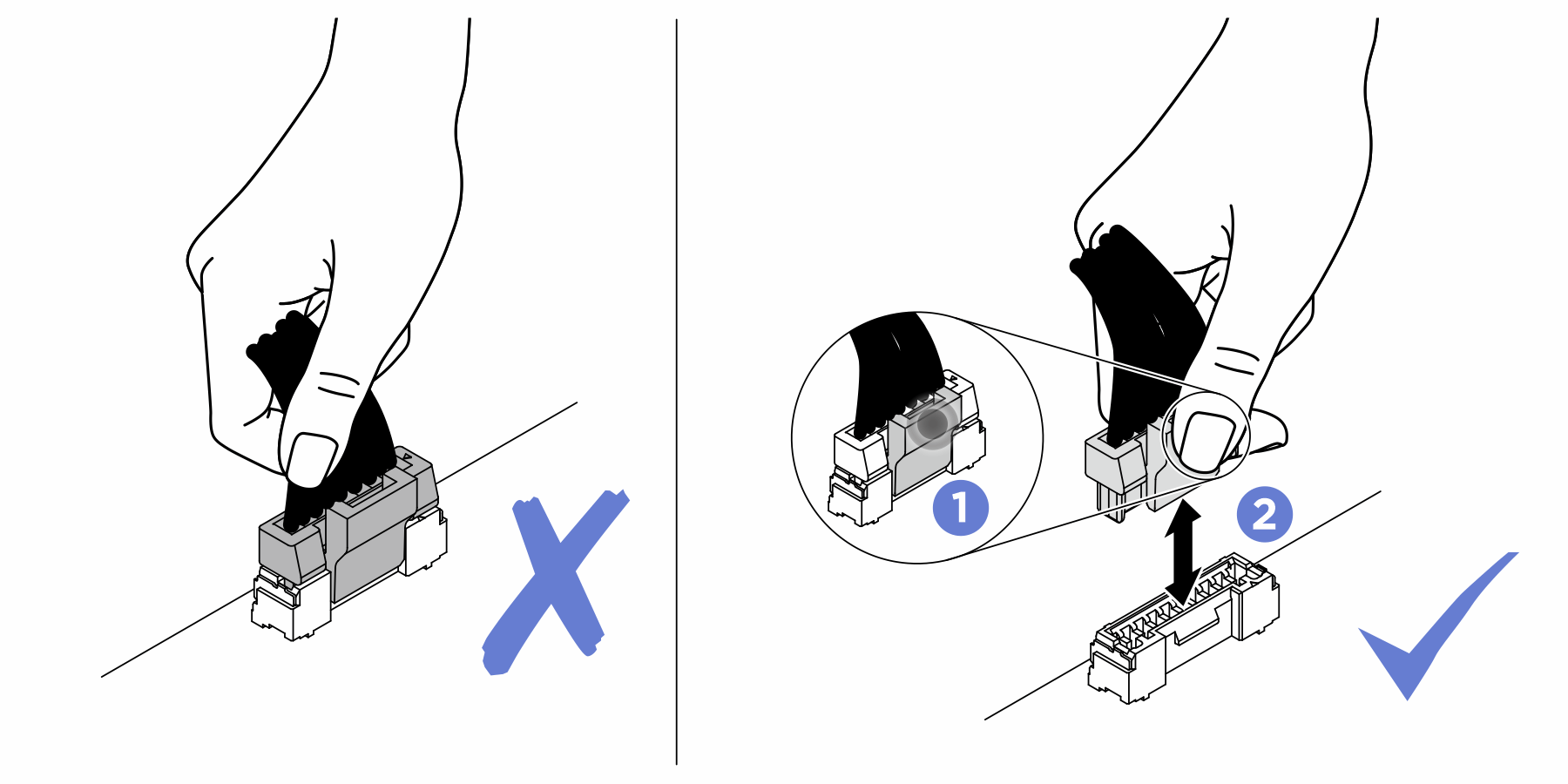
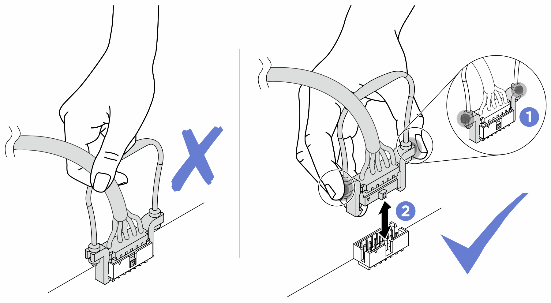
Strictly observe the following instructions to avoid damaging cable sockets on the system board. Any damage to the cable sockets might require replacing the system board.
Connect cable connectors vertically or horizontally in alignment with the orientations of the corresponding cable sockets, avoiding any tilt.
- To disconnect cables from the system board, do as follows:
Press and hold all latches, release tabs, or locks on cable connectors to release the cable connectors.
- Remove the cable connectors vertically or horizontally in alignment with the orientations of the corresponding cable sockets, avoiding any tilt.NoteThe cable connectors might look different from those in the illustration, but the removal procedure is the same.

Based on the quantity of risers installed, select the corresponding routing plan:
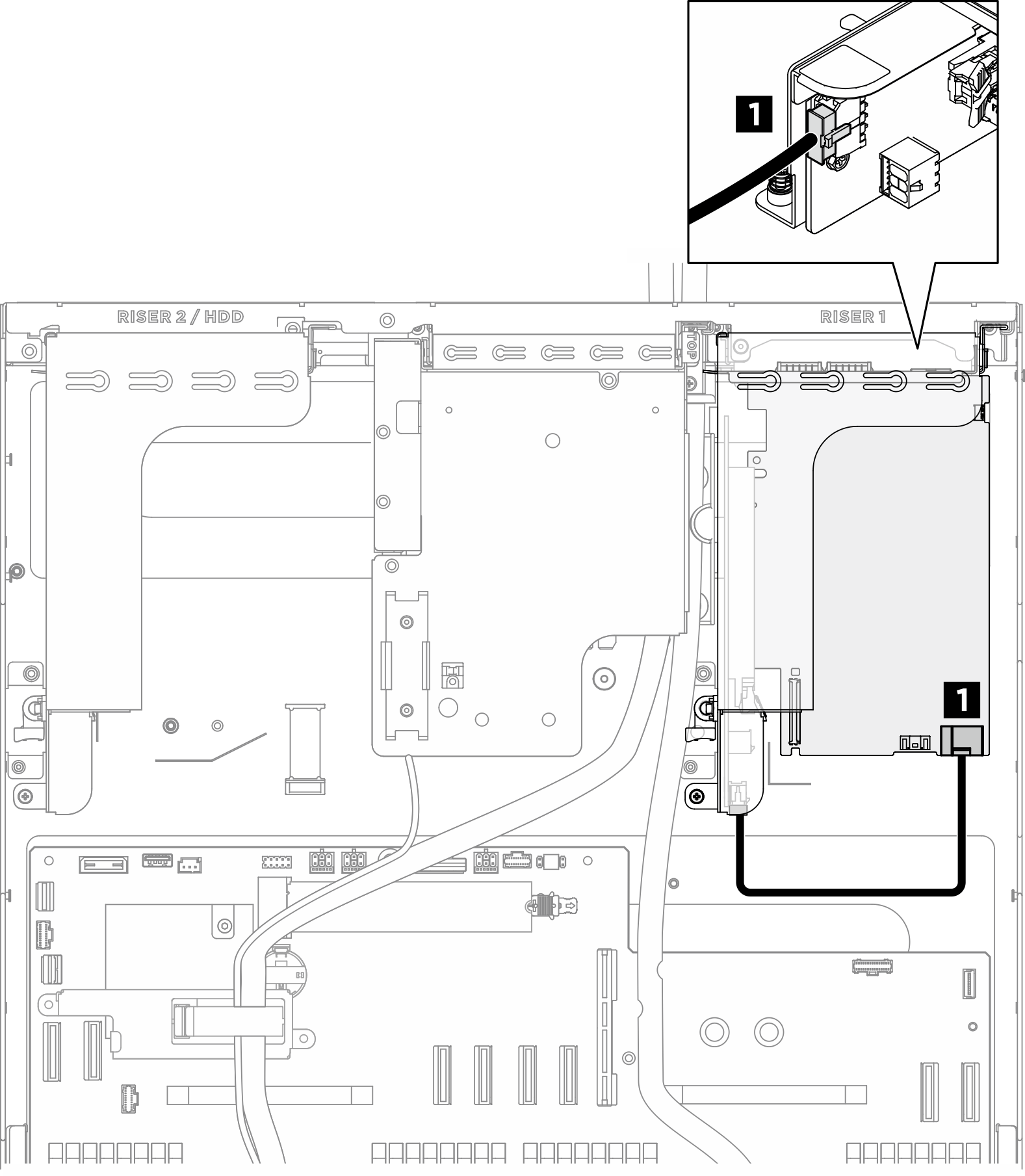
PCIe riser cable routing for two x16 PCIe risers
Figure 1. PCIe riser cable routing for two x16 PCIe risers
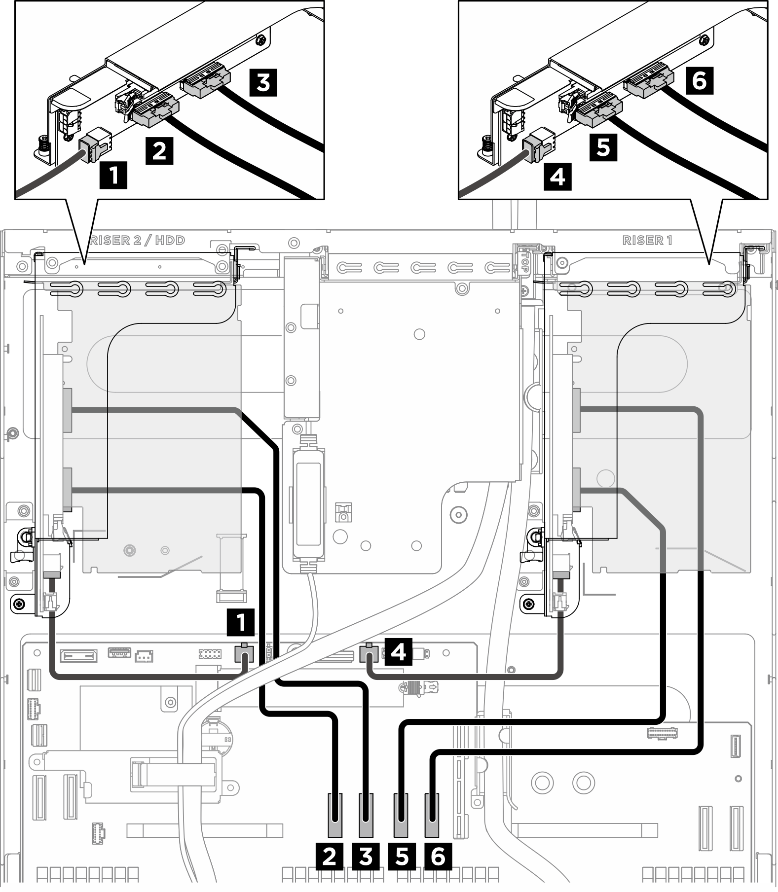
| From | To | Label |
|---|---|---|
| 1 PCIe Riser 2 power connector (RISER PWR) | System board assembly: PCIe Riser 2 power and sideband connector (BP PWR/SIG 2) |
|
| 2 PCIe riser 2 signal connector (MCIO 1) | System board assembly: PCIe Riser 2 signal connectors (MCIO4B) |
|
| 3 PCIe riser 2 signal connector (MCIO 2) | System board assembly: PCIe Riser 2 signal connectors (MCIO4A) |
|
| 4 PCIe Riser 1 power connector (RISER PWR) | System board assembly: PCIe Riser 1 power and sideband connector (BP PWR/SIG 3) |
|
| 5 PCIe riser 1 signal connector (MCIO 1) | System board assembly: PCIe Riser 1 signal connectors (MCIO8A) |
|
| 6 PCIe riser 1 signal connector (MCIO 2) | System board assembly: PCIe Riser 1 signal connectors (MCIO8B) |
|
PCIe riser cable routing for one x16 PCIe riser and two x8 PCIe risers
Figure 2. PCIe riser cable routing for one x16 PCIe riser and two x8 PCIe risers
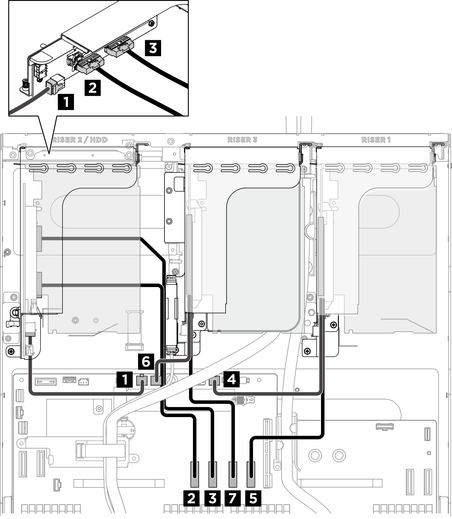
| From | To | Label |
|---|---|---|
| 1 PCIe Riser 2 power connector (RISER PWR) | System board assembly: PCIe Riser 2 power and sideband connector (BP PWR/SIG 2) |
|
| 2 PCIe riser 2 signal connector (MCIO 1) | System board assembly: PCIe Riser 2 signal connectors (MCIO4B) |
|
| 3 PCIe riser 2 signal connector (MCIO 2) | System board assembly: PCIe Riser 2 signal connectors (MCIO4A) |
|
| 4 PCIe Riser 1 cabled riser card | System board assembly: PCIe Riser 1 power and sideband connector (BP PWR/SIG 3) |
|
| 5 PCIe Riser 1 cabled riser card | System board assembly: PCIe Riser 1 signal connectors (MCIO8B) |
|
| 6 PCIe Riser 3 cabled riser card | System board assembly: PCIe Riser 3 power and sideband connector (BP PWR/SIG 1) |
|
| 7 PCIe Riser 3 cabled riser card | System board assembly: PCIe Riser 3 signal connectors (MCIO8A) |
|
DPU power cable routing
Figure 3. DPU power cable routing
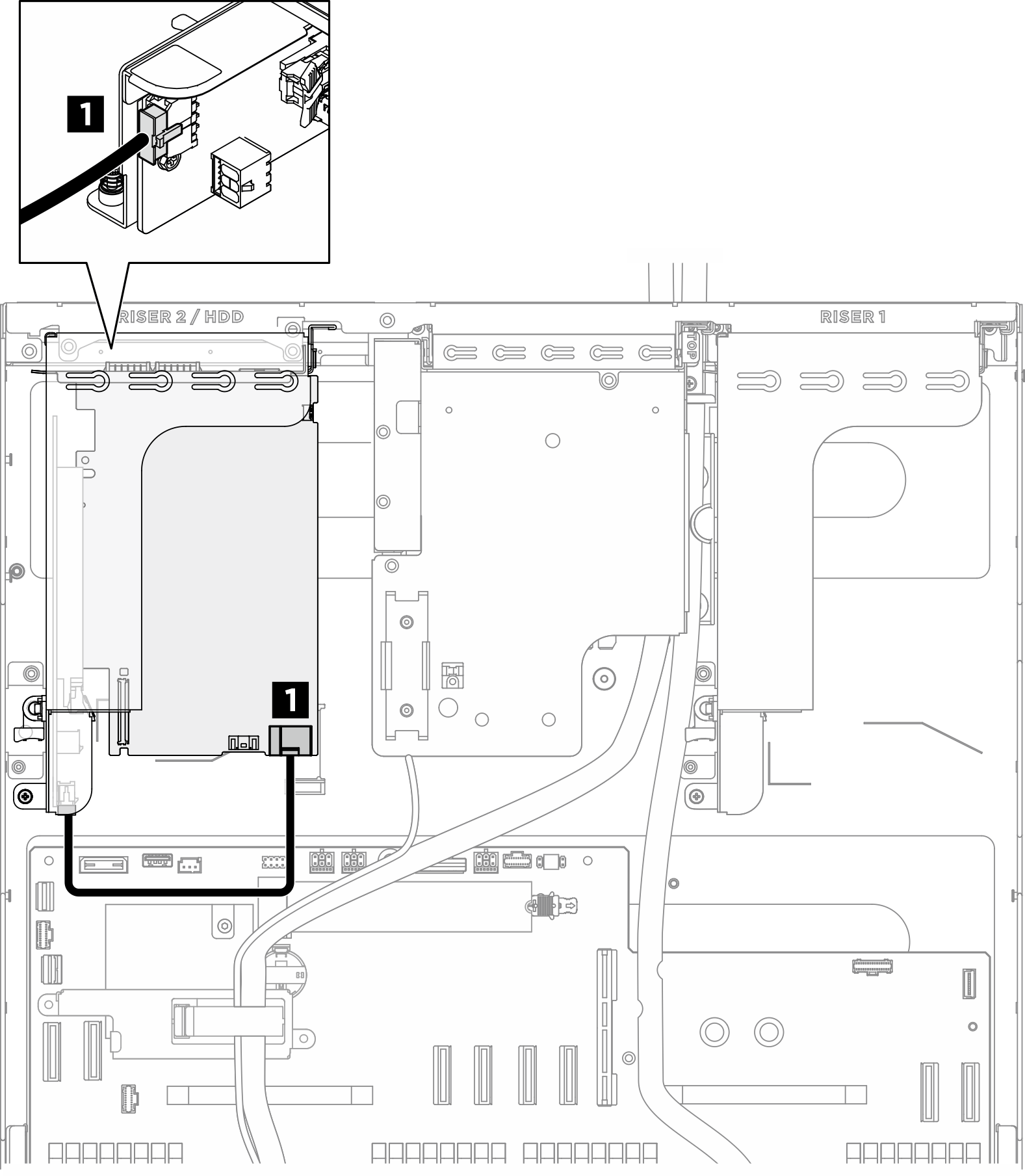
| Cable | From | To |
|---|---|---|
| 1 | DPU adapter: Power connector | PCIe riser 1 or 2: Power connector (AUX PWR) |
Give documentation feedback