2.5-inch drive backplane cable routing
Use the section to understand the cable routing for the 2.5-inch drive backplane.
Based on the location of the drive backplane, select the corresponding routing plan:
After you finish cable routing, bundle the cables with cable ties corresponding to their location:
Note
- Connections between connectors; 1↔1, 2↔2, 3↔3, ... n↔n
- When routing the cables, ensure that all cables are routed appropriately through the cable guides.
Front 2.5-inch drive backplane cable routing
Figure 1. Front 2.5-inch drive backplane signal cable routing
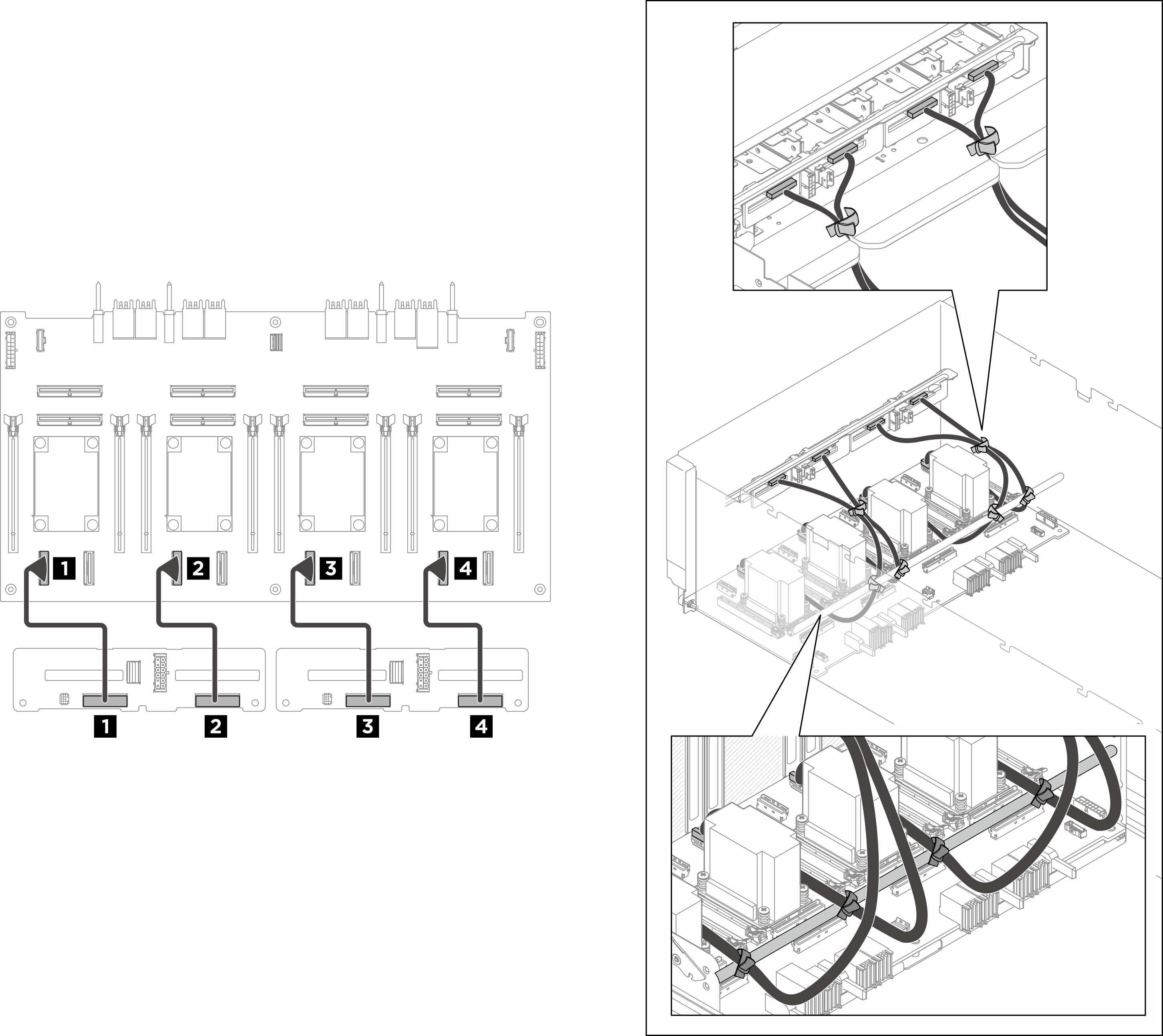
| Cable | From | To | Label |
|---|---|---|---|
| 1 | Backplane 1: NVMe connector 0-1 | PCIe switch board: NVMe connector 1 (NVME1) |
|
| 2 | Backplane 1: NVMe connector 2-3 | PCIe switch board: NVMe connector 3 (NVME3) |
|
| 3 | Backplane 2: NVMe connector 0-1 | PCIe switch board: NVMe connector 5 (NVME5) |
|
| 4 | Backplane 2: NVMe connector 2-3 | PCIe switch board: NVMe connector 7 (NVME7) |
|
Note
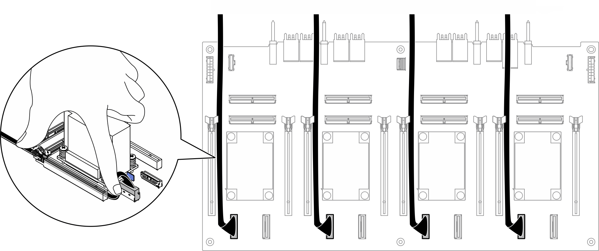
Press the 2.5-inch drive backplane signal cables down onto the board to keep them away from the heat sinks.
Attention
- For H100/H200 GPU, route the 2.5-inch drive backplane power cables through the GPU cable holder as illustrated.
- For B200 GPU, route the 2.5-inch drive backplane power cables through the hoses as illustrated.
Figure 2. Front 2.5-inch drive backplane power cable routing for H100/H200 GPU
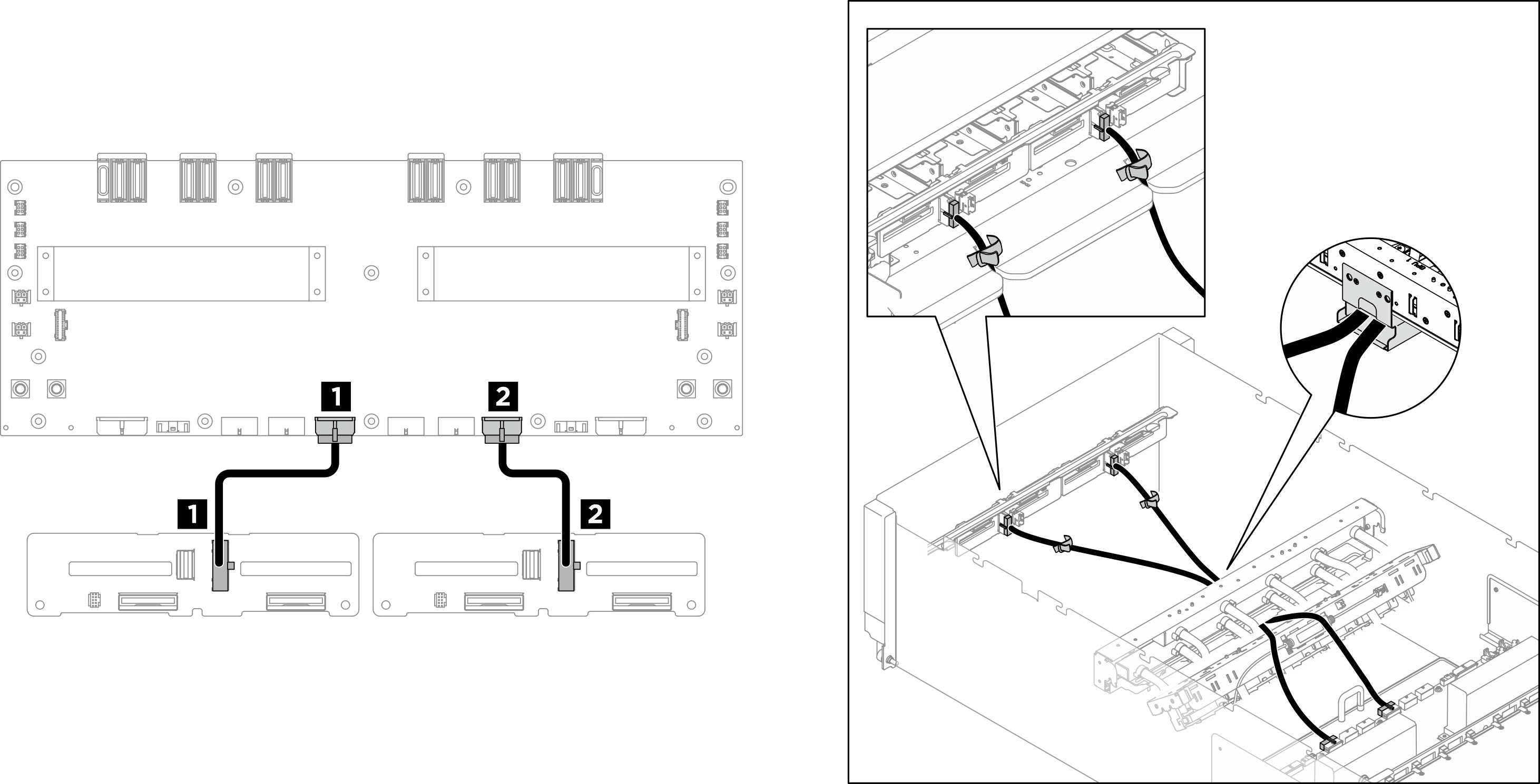
Figure 3. Front 2.5-inch drive backplane power cable routing for B200 GPU
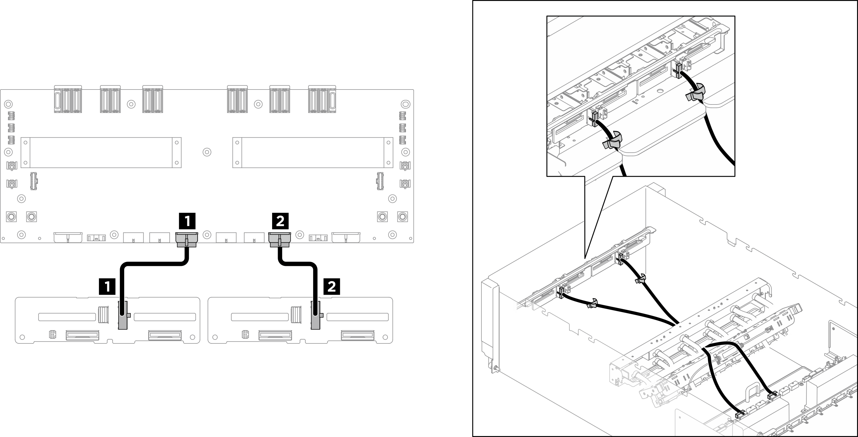
| Cable | From | To | Label |
|---|---|---|---|
| 1 | Backplane 1: Power connector | Power distribution board: Backplane 1 power connector (BP1 PWR) |
|
| 2 | Backplane 2: Power connector | Power distribution board: Backplane 2 power connector (BP2 PWR) |
|
Rear 2.5-inch drive backplane cable routing
Figure 4. Rear 2.5-inch drive backplane cable routing
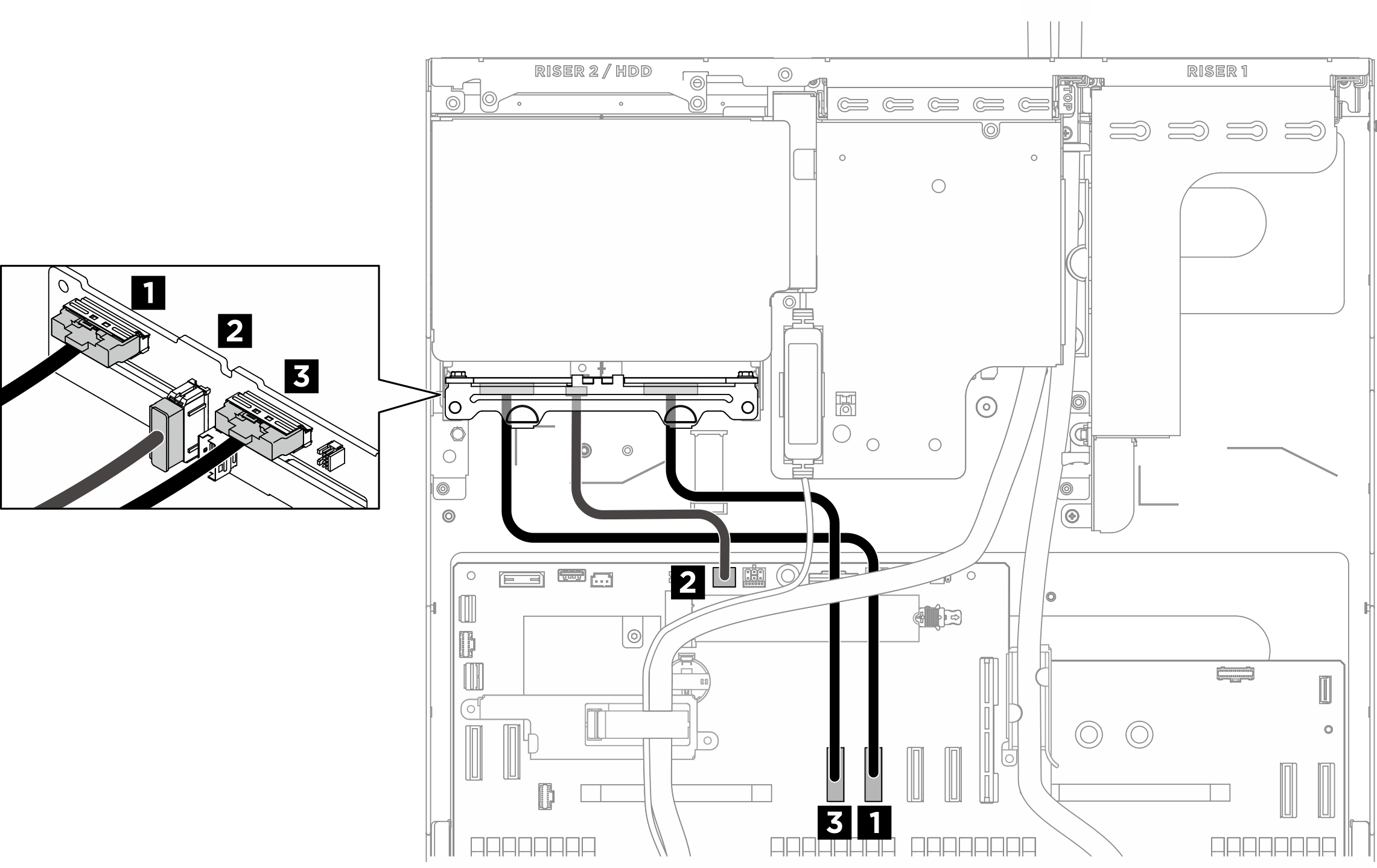
| Cable | From | To | Label |
|---|---|---|---|
| 1 | Backplane : NVMe connector 2-3 | System board: Rear drive backplane signal connector (MCIO4B) |
|
| 2 | Backplane : Power connector | System board: Rear drive backplane power connector (BP PWR/SIG 2) |
|
| 3 | Backplane : NVMe connector 0-1 | System board: Rear drive backplane signal connector (MCIO4A) |
|
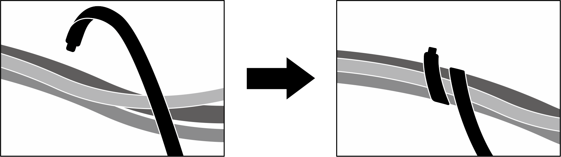
After you finish
Figure 5. Securing cables with cable ties
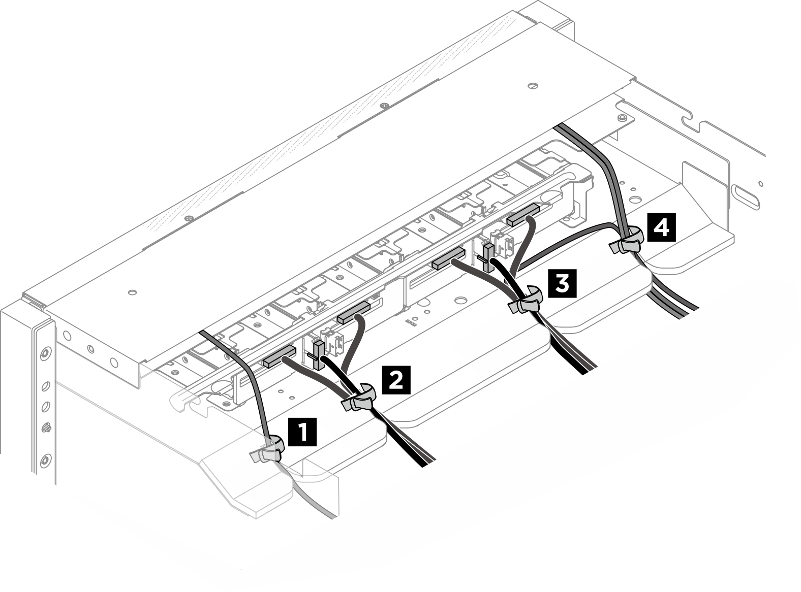
Bundle cables on the front drive backplane side
Divide the drive backplane signal and power cables, GPU management cable, front I/O module cables, and integrated diagnostics panel cable into four bundles, and secure them with cable ties as illustrated.
| Bundle | Cable | Connector |
| 1 |
|
|
| 2 |
|
|
| 3 |
|
|
| 4 |
|
|
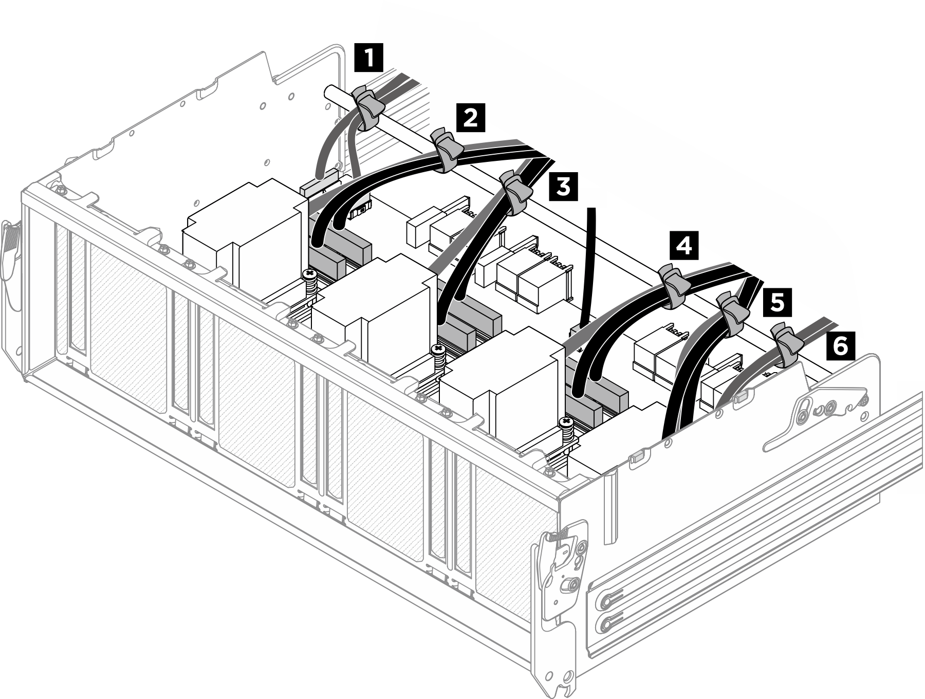
Bundle cables connected to the PCIe switch board
Divide the cables connected to the PCIe switch board into six bundles, and secure them to the crossbar with cable ties.
| Bundle | Cable | Connector (on PCIe switch board) |
| 1 |
|
|
| 2 |
|
|
| 3 |
|
|
| 4 |
|
|
| 5 |
|
|
| 6 |
|
|
Give documentation feedback