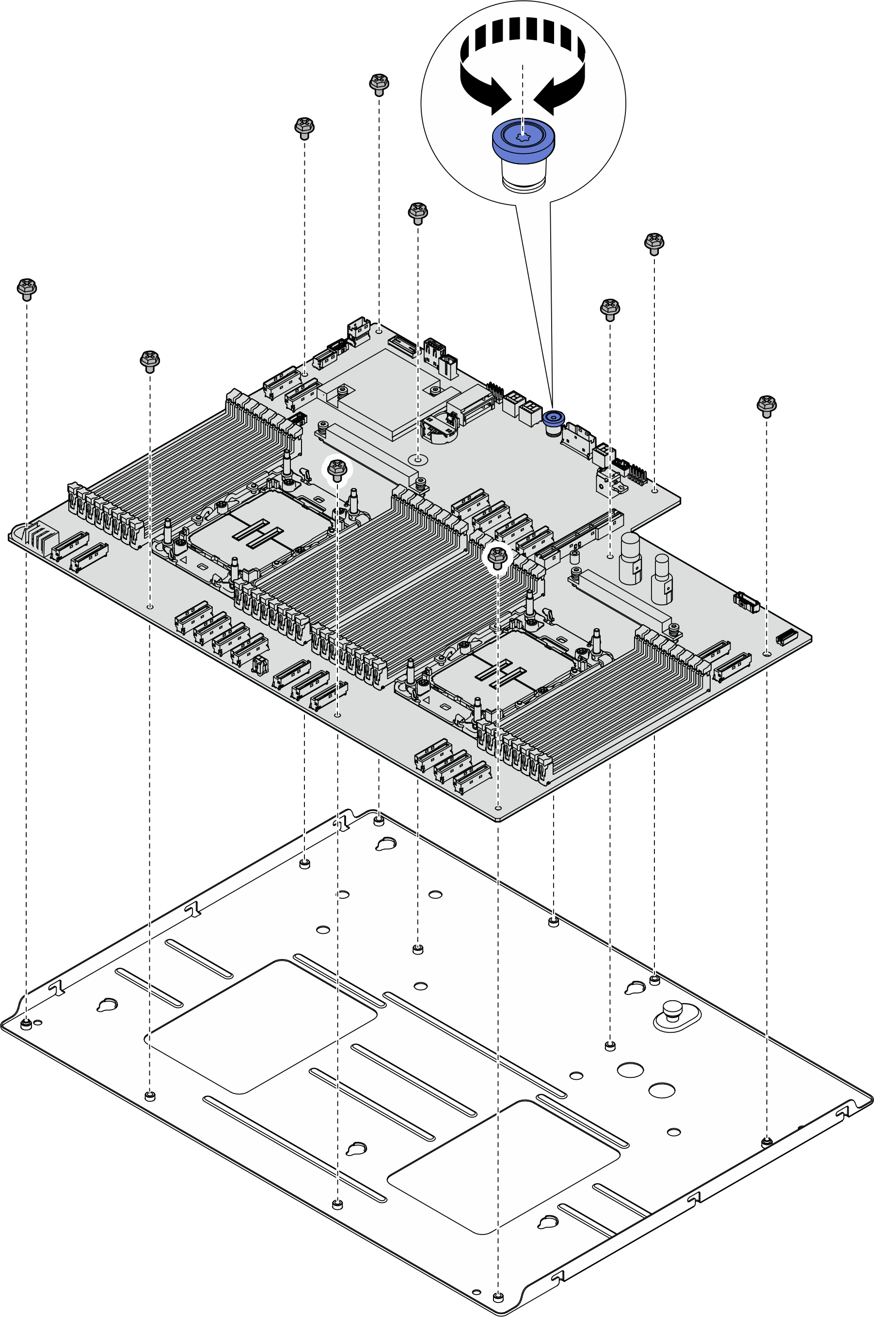
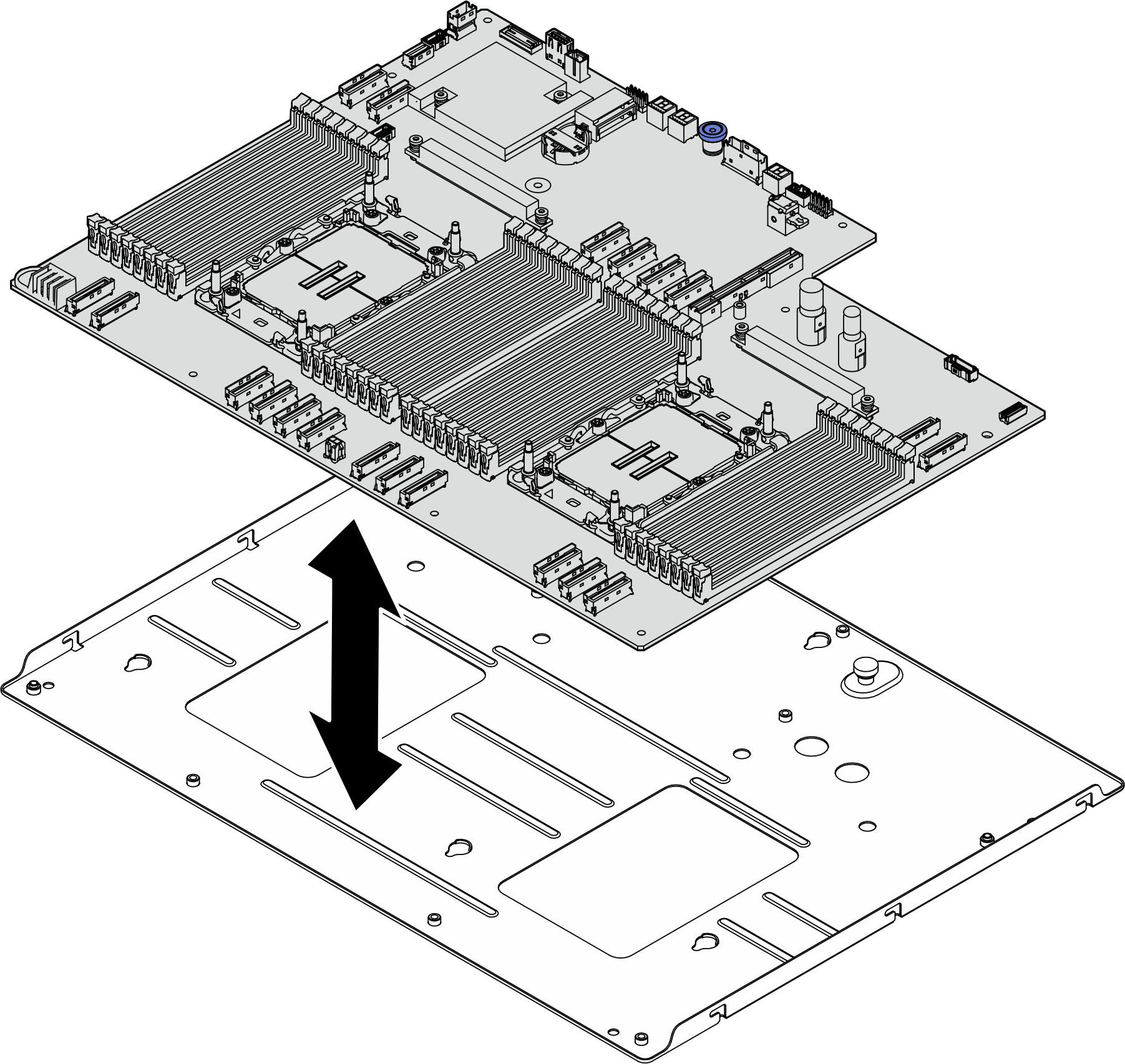
Disassemble the system board for recycle
Follow the instructions in this section to disassemble the system board before recycling.
About this task
Before disassembling the system board:
- Remove the processor air baffle. See Remove the processor air baffle.
- If applicable, remove the PCIe riser assembly(ies). See Remove a PCIe riser assembly.
- If applicable, remove the rear drive cage. See Remove the rear drive cage.
- If applicable, remove the DPU air baffle. See Remove the DPU air baffle.
- If applicable, remove the leakage sensor module bracket. See Remove the leakage sensor module bracket.
- If applicable, remove the system I/O board. See Remove the system I/O board.
- Remove the Lenovo Processor Neptune® Core Module. See Remove the Lenovo Processor Neptune® Core Module.
- Remove all the memory modules. See Remove a memory module.
- Remove the CMOS battery (CR2032). See Remove the CMOS battery (CR2032).
- Refer to local environmental, waste or disposal regulations to ensure compliance.
Procedure
After you finish
After disassembling the system board assembly, recycle the unit in compliance with local regulations.
Give documentation feedback
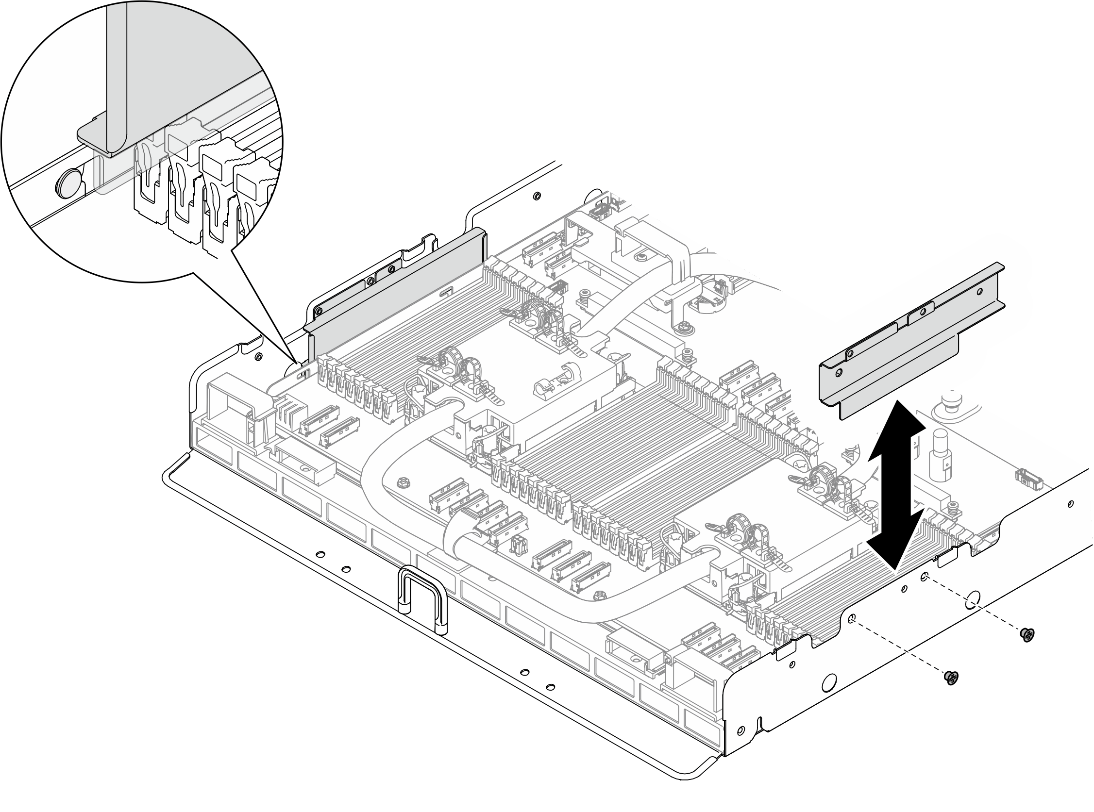
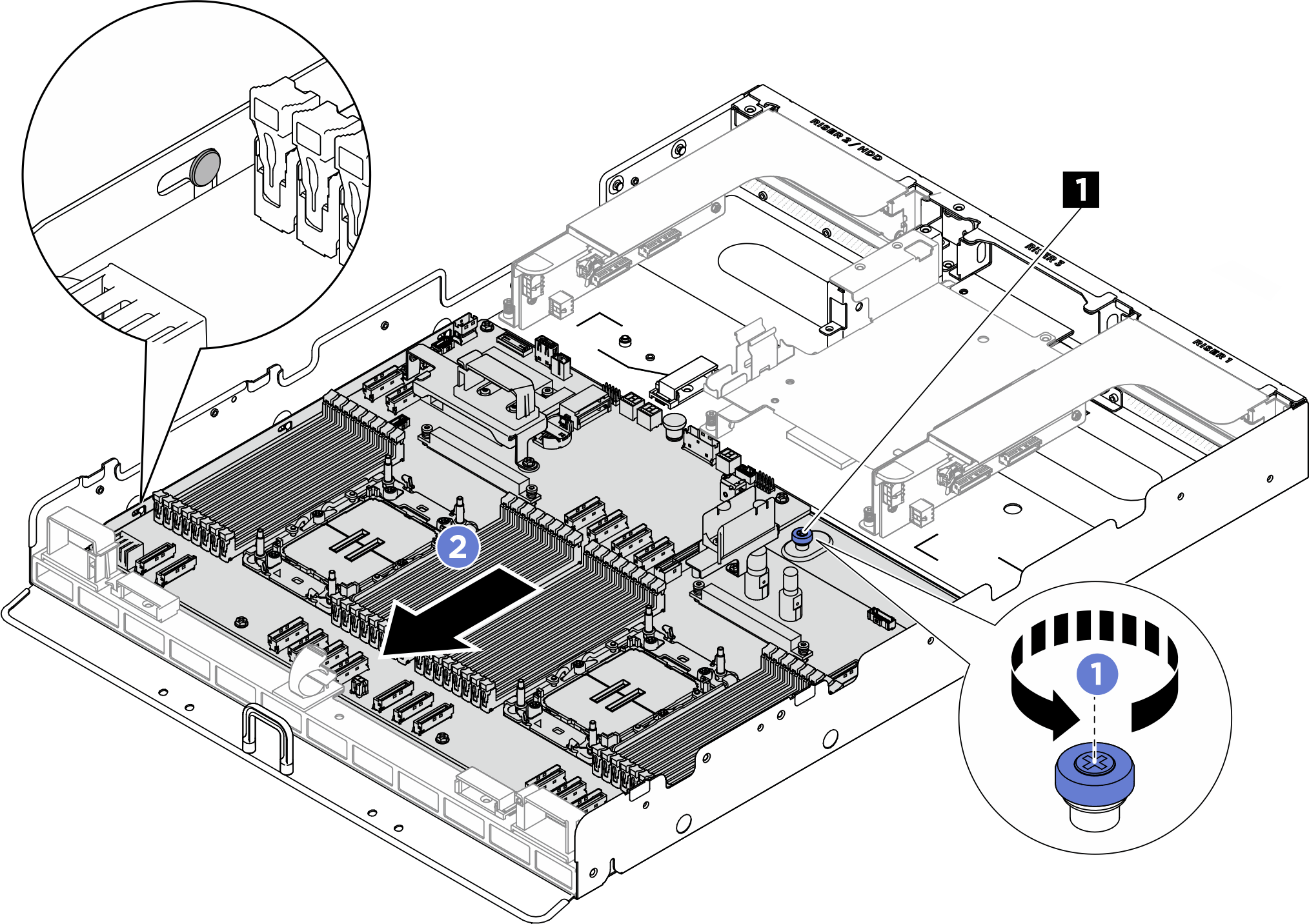
 Loosen the (1) thumbscrew to release the system board.
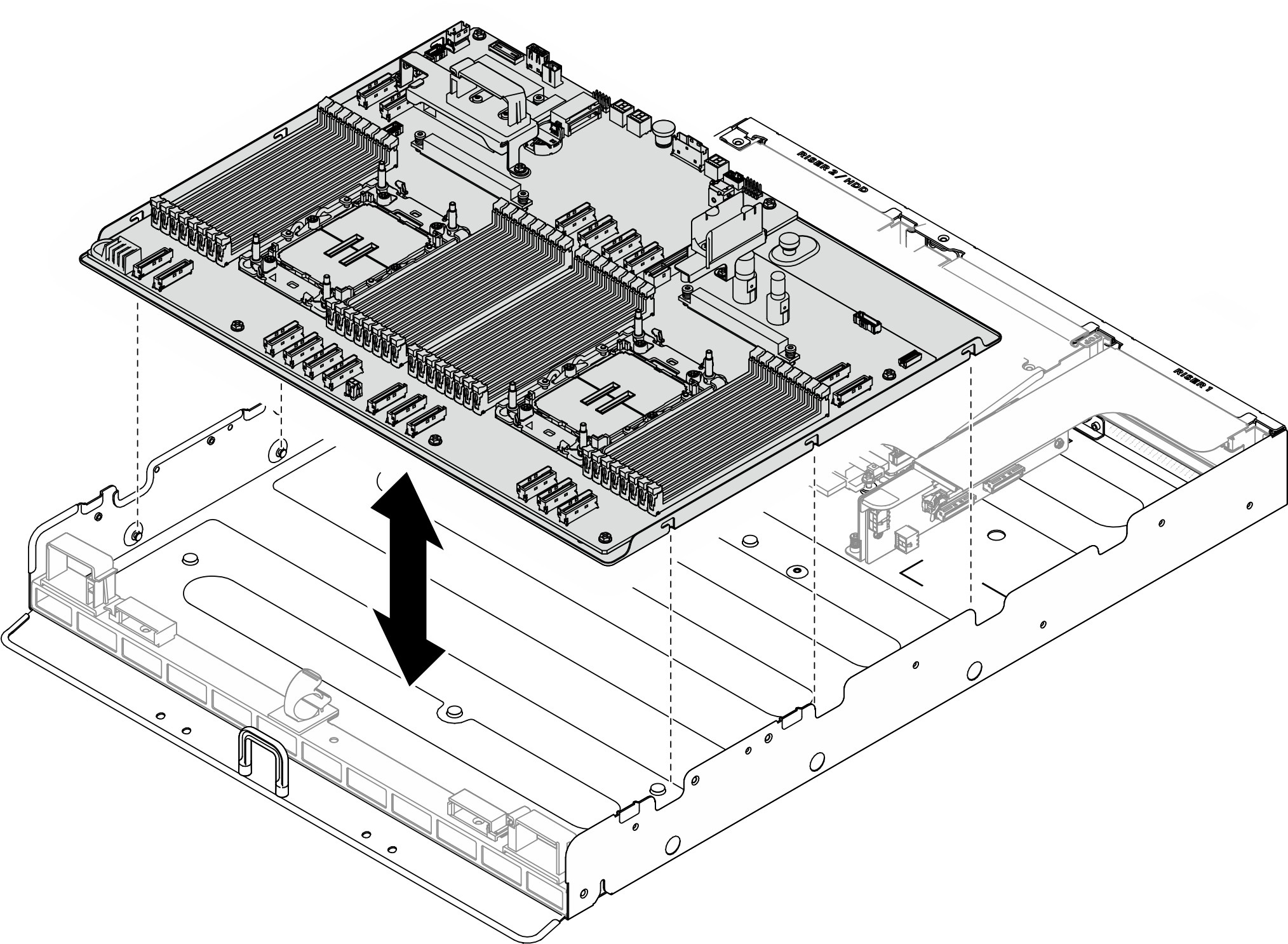
 Slide the system board towards the front of the CPU complex as illustrated to disengage it from the chassis.