Remove the Lenovo Processor Neptune® Core Module
Follow the instructions in this section to remove the Lenovo Processor Neptune® Core Module. The procedure must be executed by a trained technician.
About this task
Safety information for leakage sensor module cable
S011

CAUTION
Sharp edges, corners, or joints nearby.
Attention
Read Installation Guidelines and Safety inspection checklist to ensure that you work safely.
Prevent exposure to static electricity, which might lead to system halt and loss of data, by keeping static-sensitive components in their static-protective packages until installation, and handling these devices with an electrostatic-discharge wrist strap or other grounding system.
- Power off the server and peripheral devices and disconnect the power cords and all external cables. See Power off the server.
- If the server is installed in a rack, slide the server out on its rack slide rails to gain access to the top cover, or remove the chassis from the rack. See Remove the server from rack.
- Two people and one lifting device on site that can support up to 400 lb (181 kg) are required to perform this procedure. If you do not already have a lifting device available, Lenovo offers the Genie Lift GL-8 material lift that can be purchased at Data Center Solution Configurator. Make sure to include the Foot-release brake and the Load Platform when ordering the Genie Lift GL-8 material lift.
Depending on the specific configuration, the hardware might look slightly different from the illustrations in this section.
Prepare the following screwdrivers to ensure you can install and remove the corresponding screws properly.
| Torque screwdriver type list | Screw Type |
|---|---|
| Torx T30 head screwdriver | Torx T30 screw |
Procedure
- Disengage the leakage sensor module.
- Push the holder latches to both sides to unlock the module.
- Disengage the leakage sensor module from the holder.
Figure 1. Disengage the leakage sensor module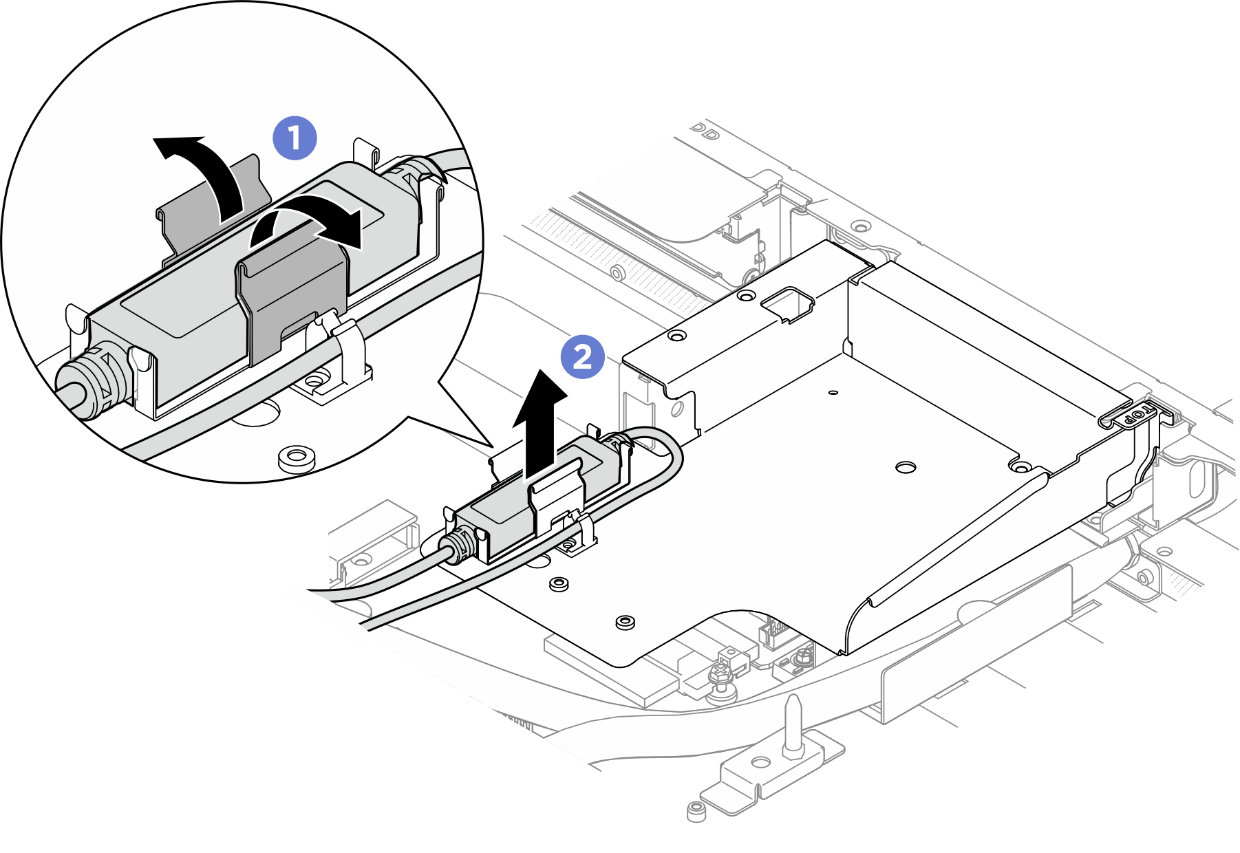
- Remove the leakage sensor module bracket. Refer to Remove the leakage sensor module bracket for leakage sensor module bracket removal with different configurations.
- Unfasten the four M3 screws that secure the leakage sensor module bracket to the chassis.
- Grasp the bracket and lift it from the chassis.
Figure 2. Removing the leakage sensor module bracket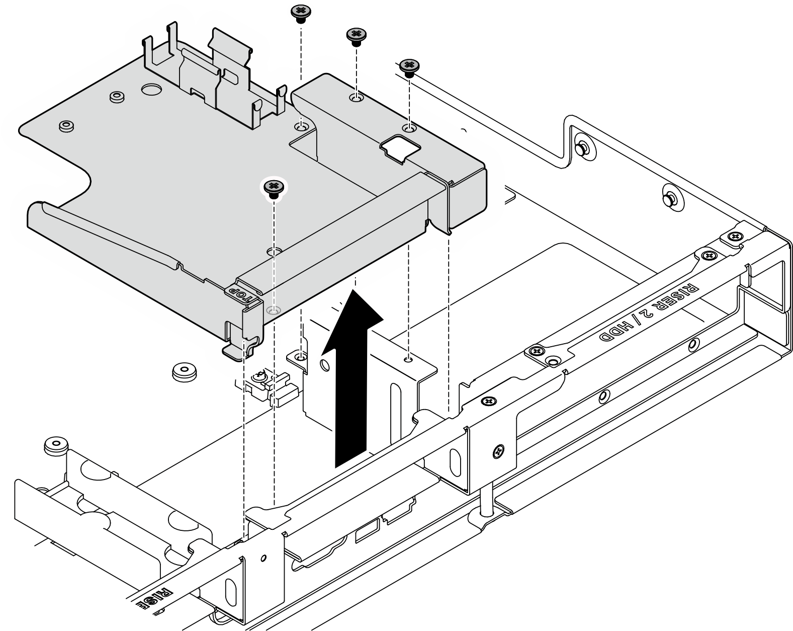
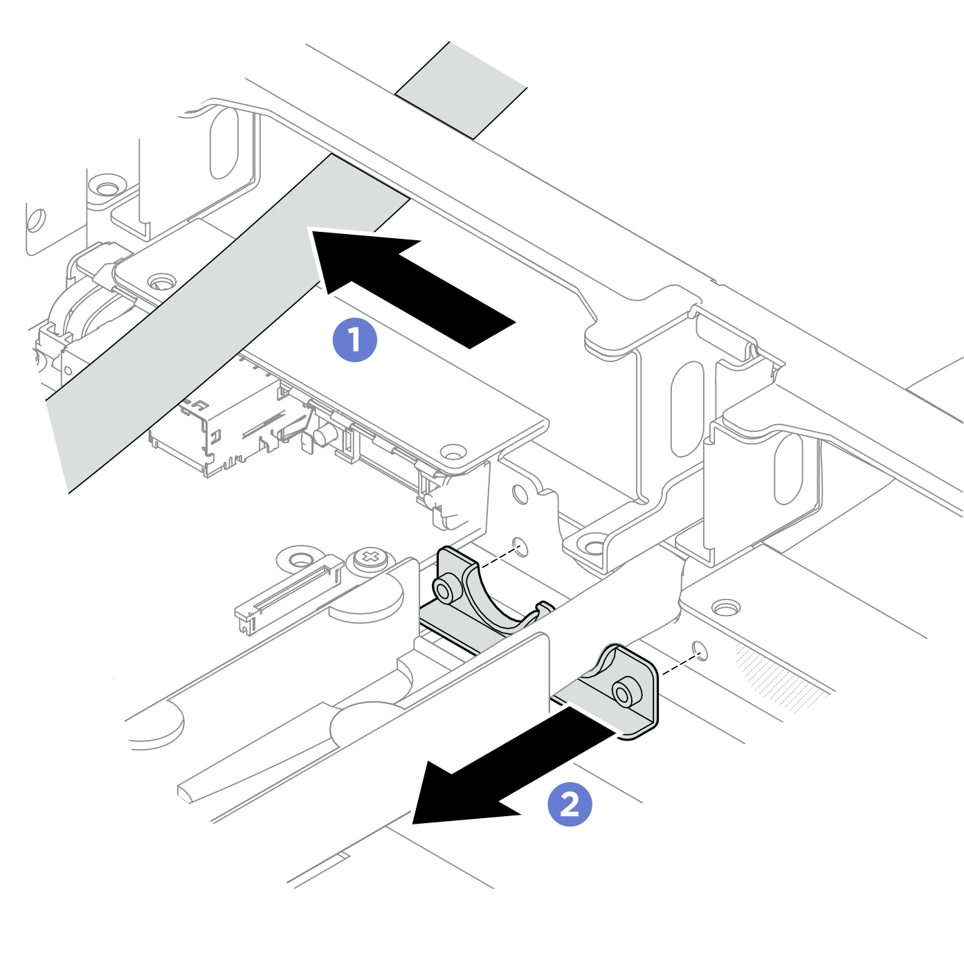
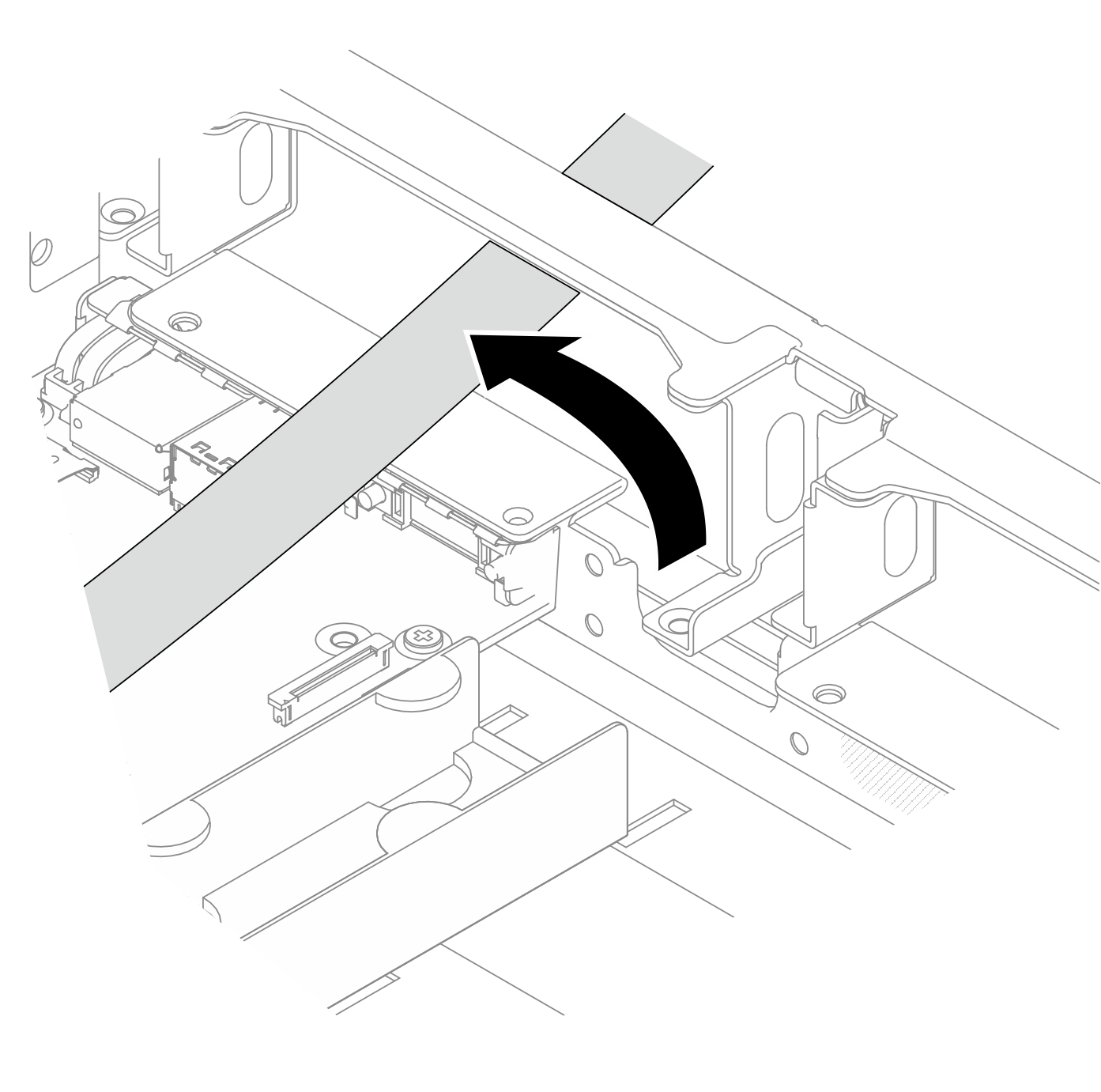
- Remove the hose cover.
 Unfasten the three M3 screws that secure the hose cover to the chassis.
 Disengage the hose cover from the hose opening on the chassis by sliding it away from the opening; then, remove it from the chassis.
Figure 3. Removing hose cover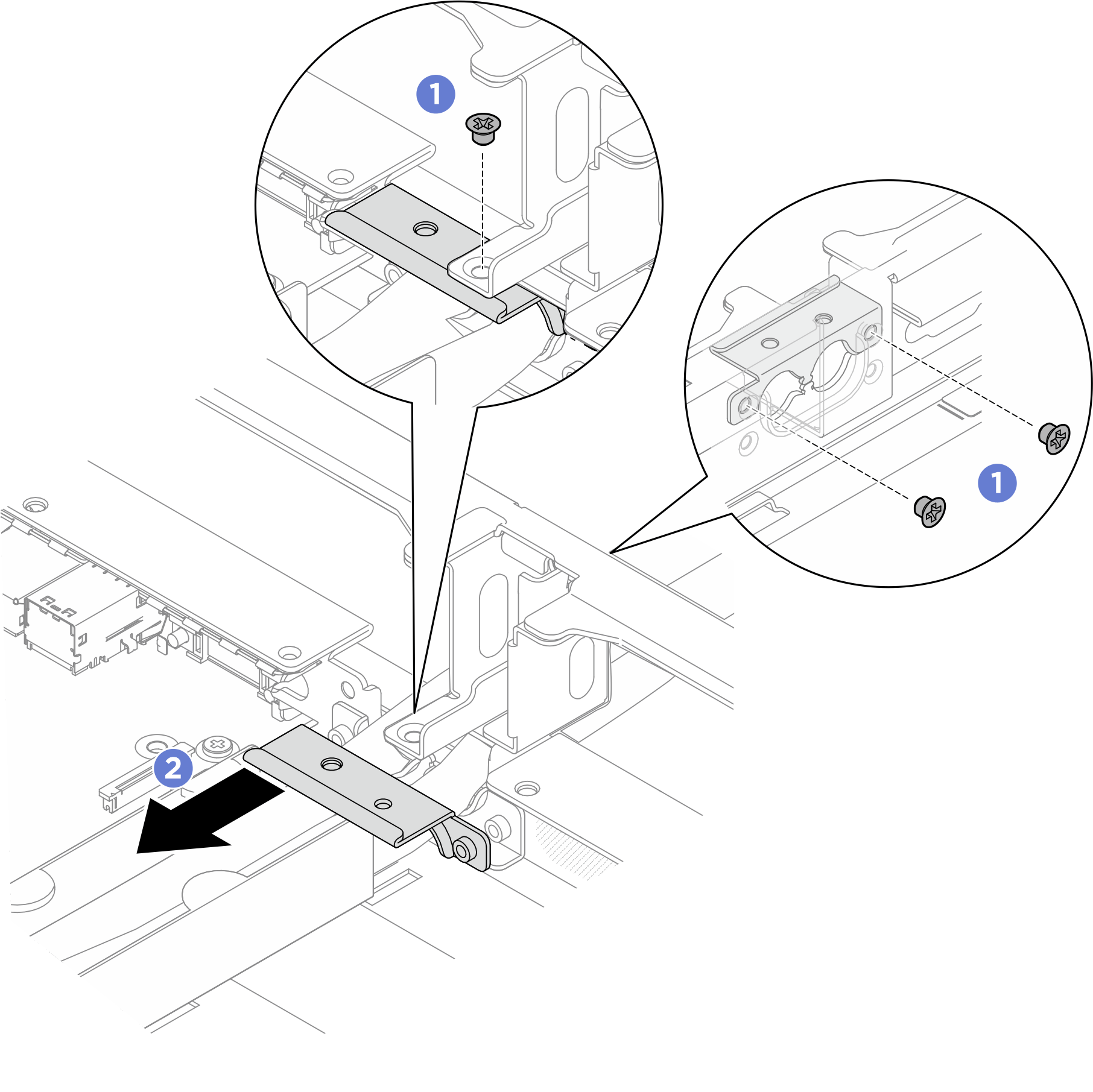
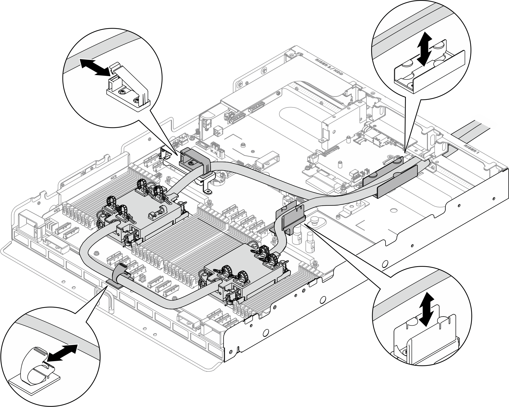
- Remove the hoses.
- Disengage the hoses from the hose clips and holders.Figure 4. Disengaging the hoses
- Unfasten the two M3 screws that secure the hose holder to the chassis.Figure 5. Removing the hose holder
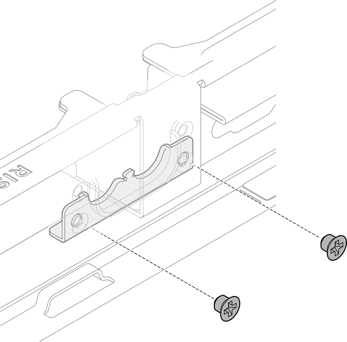
- Disengage the first hose from the hose holder as illustrated; then, remove the hose holder from the hose opening on the chassis by sliding it towards the front of the chassis.
- Remove the hose holder from the hose opening on the chassis by sliding it away from the opening.Figure 6. Disengaging the hose
- Remove the second hose through the opening.Figure 7. Removing the hose
- Disengage the hoses from the hose clips and holders.
- Remove the cold plate top covers.NoteRemove the four memory modules adjacent to the heat sinks to avoid damage. Record each memory module before removing it.Figure 8. Removing the cold plate top covers
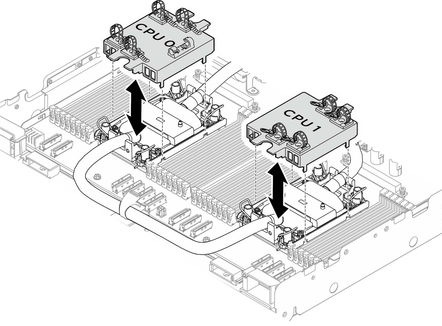
- Remove the Processor Neptune® Core Module from the processor board.
- Fully loosen the Torx T30 nuts on the cold plate assembly. (For reference, the torque required for the fasteners to fully loosen is 1.1±0.2 newton-meters, 10±2.0 inch-pounds).
- Rotate the anti-tilt wire bails inward.
 Carefully lift the Processor Neptune® Core Module from the processor sockets. If the module cannot be fully lifted out of the socket, further loosen the Torx T30 nuts and try lifting the module again.Figure 9. Removing the Processor Neptune® Core Module
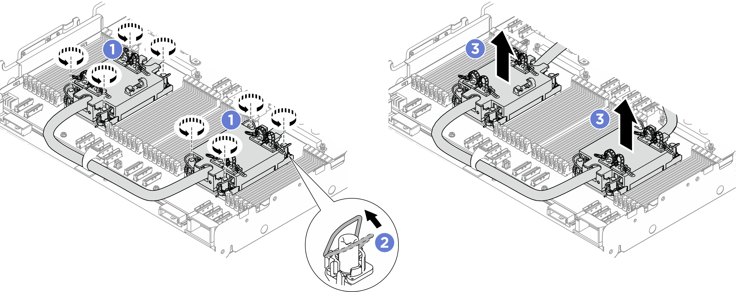
- Remove the processor from the retainer.
- Lift the handle to release the processor from the carrier.
- Hold the processor by its edges; then, lift the processor from the cold plate and carrier.
- Without putting the processor down, wipe the thermal grease from the top of the processor with an alcohol cleaning pad; then, place the processor on a static protective surface with the processor-contact side up.Figure 10. Removing the processor
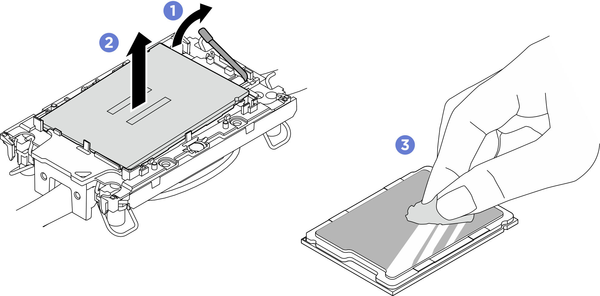 NoteDo not touch the contacts on the processor.
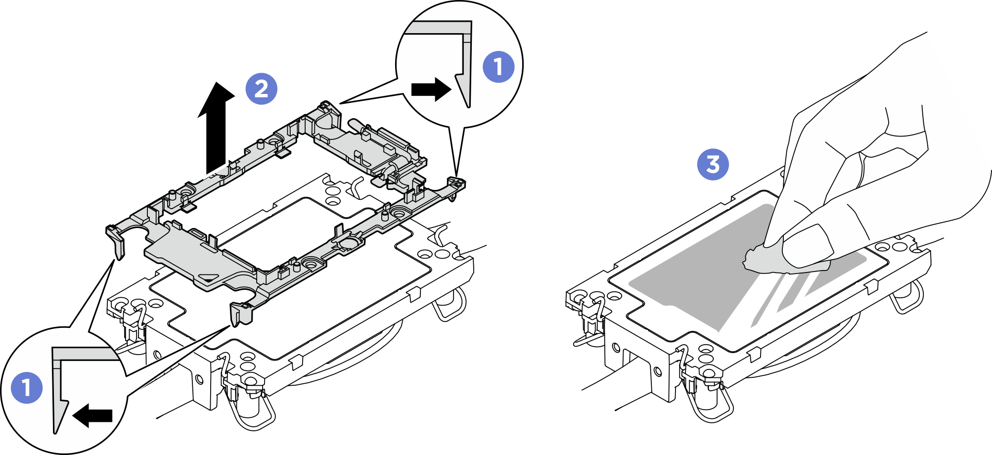
- Separate the processor carrier from the cold plate.
- Release the retaining clips from the cold plate.
- Lift the carrier from the cold plate.
- Wipe the thermal grease from the bottom of the cold plate with an alcohol cleaning pad.Figure 11. Separating a processor carrier from the cold plate
 NoteThe processor carrier will be discarded and replaced with a new one.
After you finish
- Each processor socket must always contain a cover or a processor and cold plate assembly. Protect empty processor sockets with a cover or install a new a processor and cold plate assembly.
- If you are removing the processor and cold plate assembly as part of a system board assembly replacement, set the processor and cold plate assembly aside.
- Install a replacement unit (seeInstall the Lenovo Processor Neptune® Core Module).
- If you are instructed to return the component or optional device, follow all packaging instructions, and use any packaging materials for shipping that are supplied to you.
Give documentation feedback