Install the Lenovo Processor Neptune® Core Module
Follow the instructions in this section to install the Lenovo Processor Neptune® Core Module. The procedure must be executed by a trained technician.
About this task

Read Installation Guidelines and Safety inspection checklist to ensure that you work safely.
Power off the server and peripheral devices and disconnect the power cords and all external cables. See Power off the server.
Prevent exposure to static electricity, which might lead to system halt and loss of data, by keeping static-sensitive components in their static-protective packages until installation, and handling these devices with an electrostatic-discharge wrist strap or other grounding system.
| Torque screwdriver type list | Screw Type |
|---|---|
| Torx T30 head screwdriver | Torx T30 screw |
Procedure
- If you are replacing the cold plate and reusing the processor.
- Install processor in new carrier.
 Make sure the handle on the carrier is in the closed position.
 Align the processor on the new carrier so that the triangular marks align; then, insert the marked end of the processor into the carrier.
 Hold the inserted end of the processor in place; then, pivot the unmarked end of the carrier down and away from the processor.
 Press the processor and secure the unmarked end under the clip on the carrier.
 Carefully pivot the sides of the carrier down and away from the processor.
 Press the processor and secure the sides under the clips on the carrier.NoteTo prevent the processor from falling out of the carrier, keep the processor-contact side up and hold the processor-carrier assembly by the sides of the carrier.Figure 1. Processor carrier installation
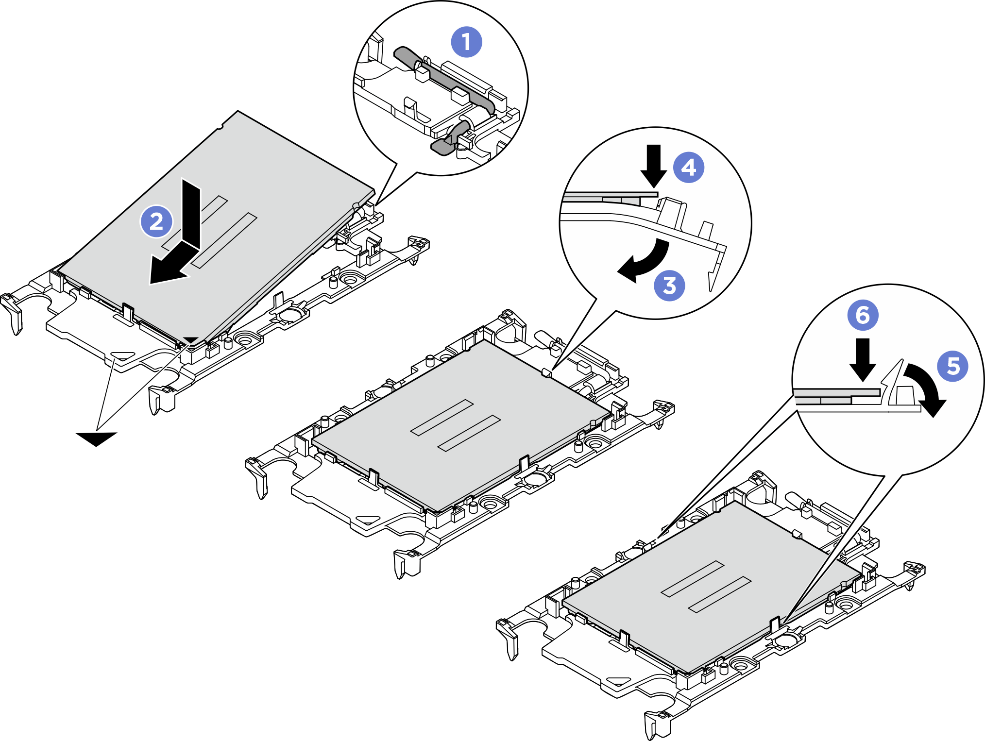
- Install processor in new carrier.
- Apply thermal grease.
- If you are replacing the heat sink and reusing the processor, a new heat sink comes with thermal grease and you do not need to apply new thermal grease.NoteTo ensure the best performance, check the manufacturing date on the new heat sink and make sure it does not exceed two years. Otherwise, wipe off the existing thermal grease and apply new thermal grease.
- If you are replacing the processor and reusing the heat sink, do the following steps to apply thermal grease:
- If there is any old thermal grease on the heat sink, wipe off the thermal grease with an alcohol cleaning pad.
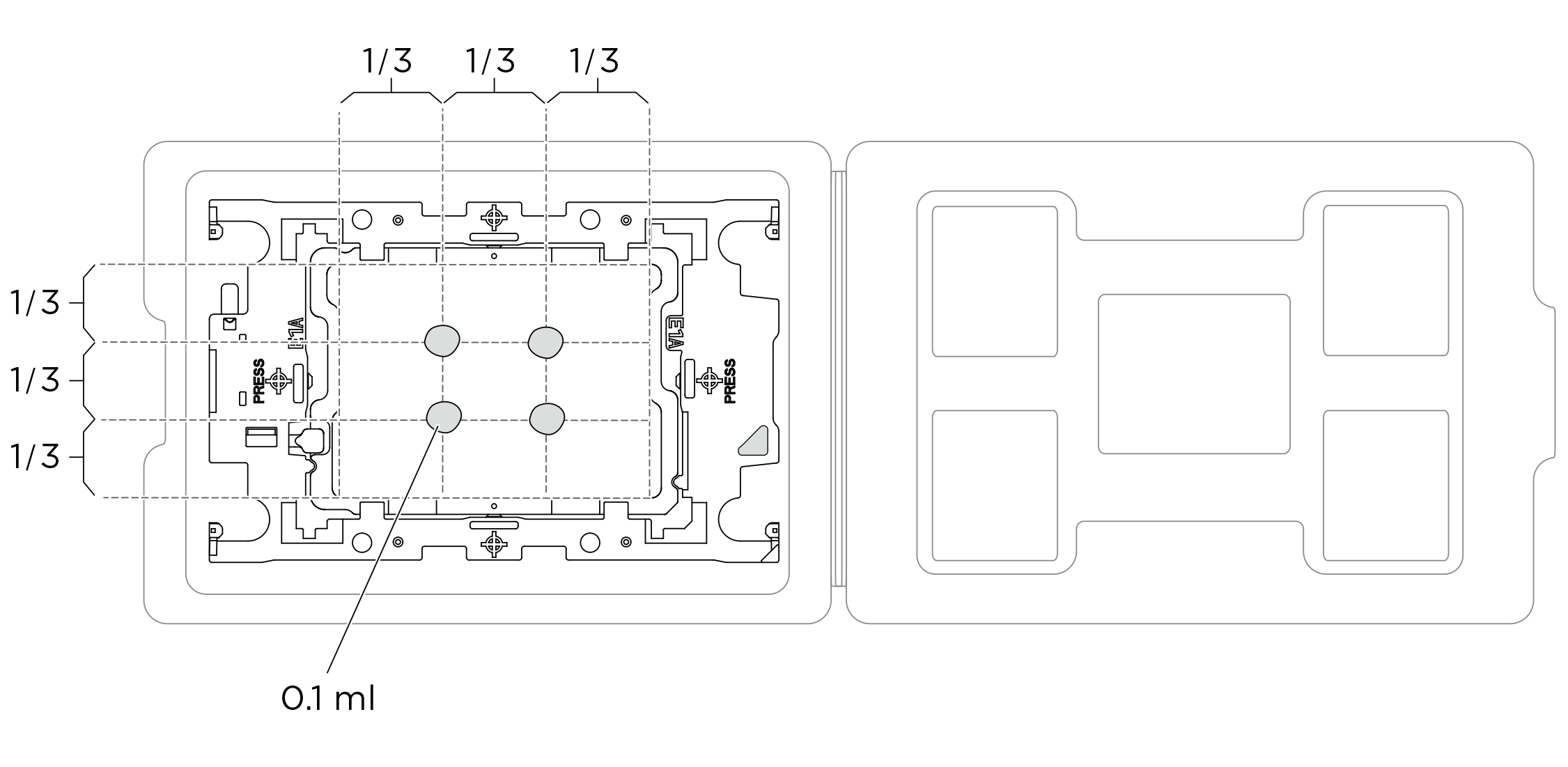
- Carefully place the processor and carrier in the shipping tray with the processor-contact side down. Make sure the triangular mark on the carrier is oriented in the shipping tray as shown below.
- Apply the thermal grease on the top of the processor with syringe by forming four uniformly spaced dots, while each dot consists of about 0.1 ml of thermal grease.Figure 2. Thermal grease application with processor in shipping tray
- If you are replacing the heat sink and reusing the processor, a new heat sink comes with thermal grease and you do not need to apply new thermal grease.
- Align the triangular marks on the processor retainers with the triangular slots on the underside of the cold plate; then, attach the processors to the underside of the cold plate by inserting the processor retainer posts and clips features into the openings at the four corners of the cold plate.Figure 3. Assembling the processor with cold plate
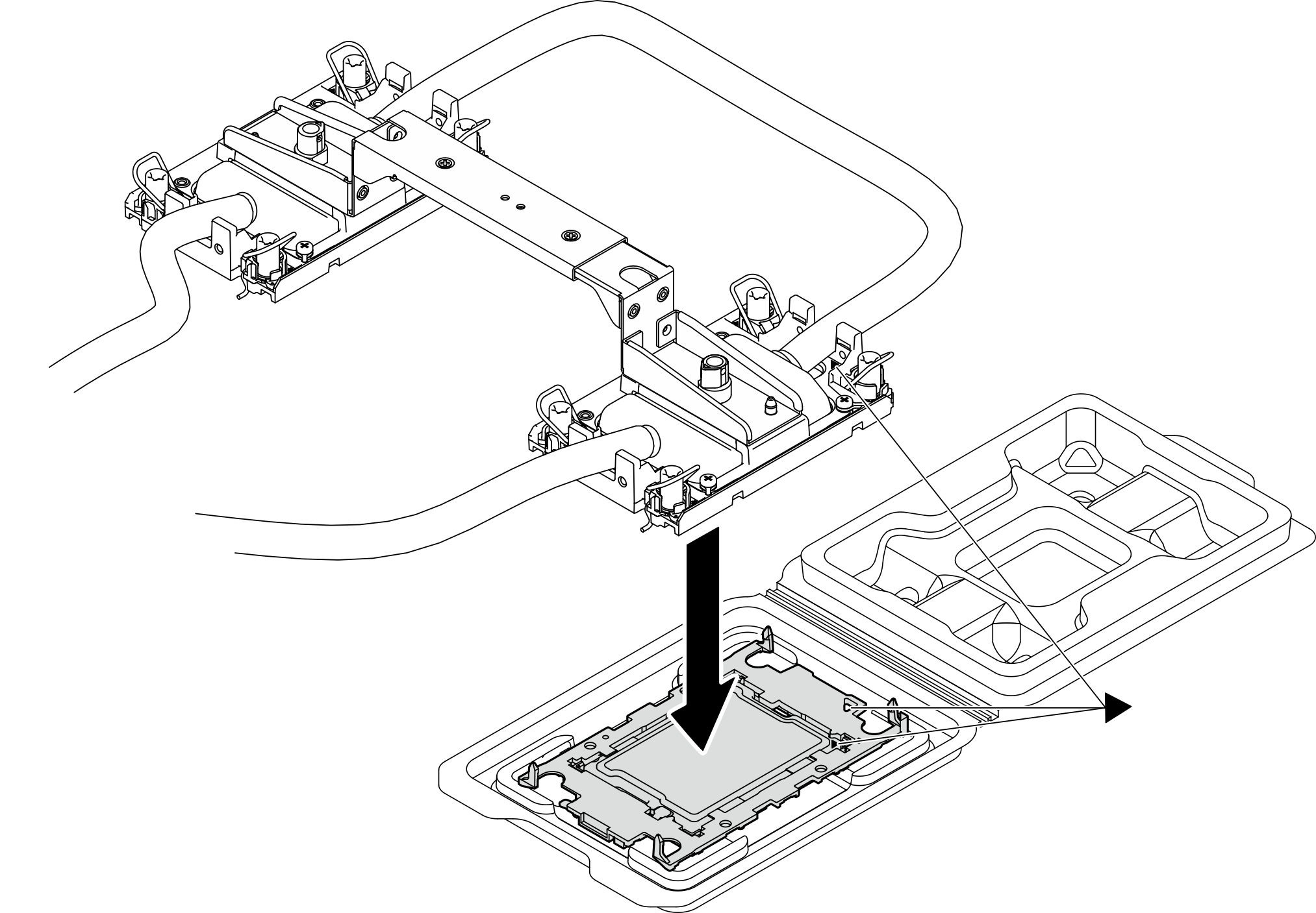 Figure 4. Inspecting the processor with cold plate
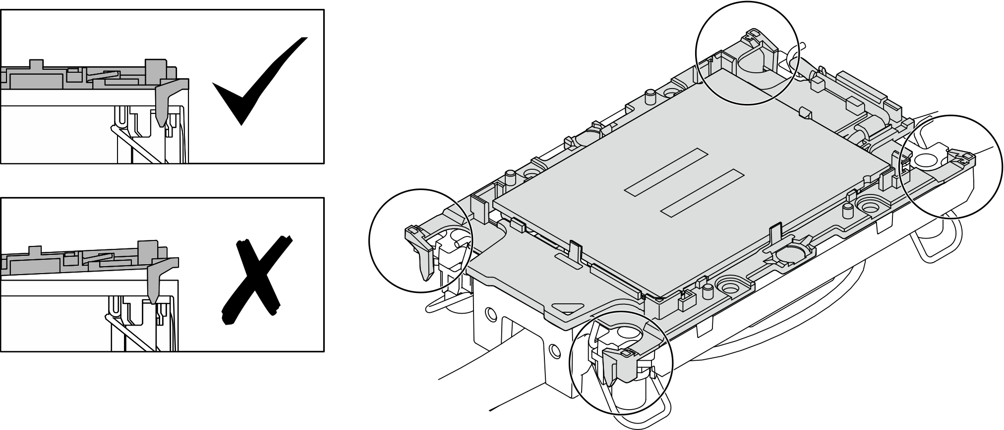
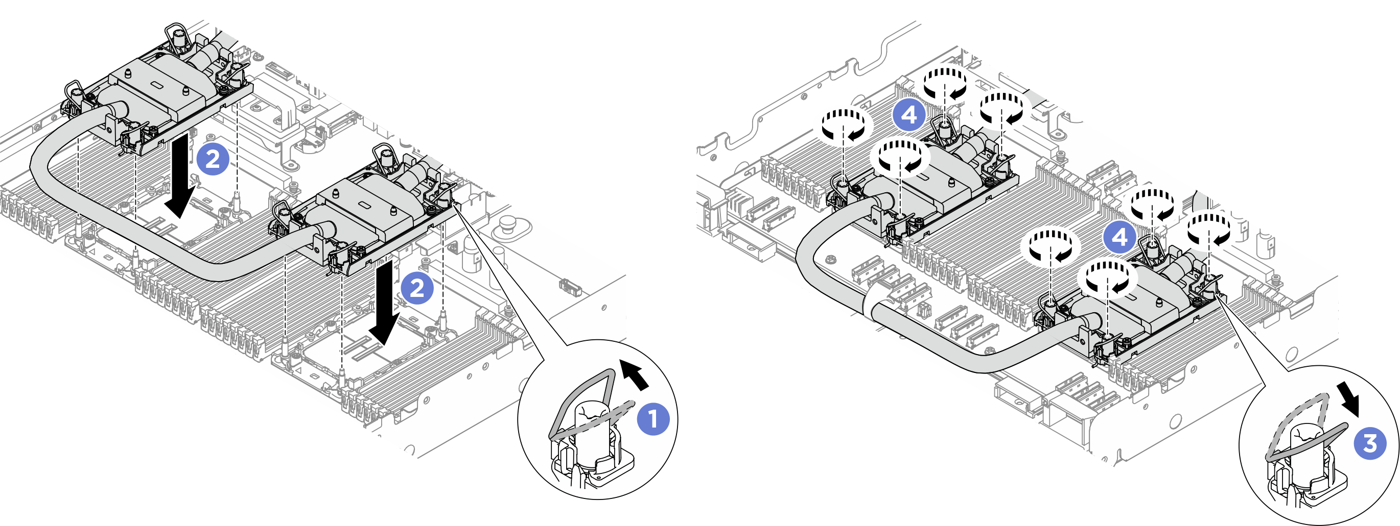
- Install the Processor Neptune® Core Module to the system board assembly.
- Rotate the anti-tilt wire bails inward.
- Align the triangular mark and four Torx T30 nuts on the cold plate assembly with the triangular mark and threaded posts of the processor socket; then, insert the cold plate assembly into the processor socket.
- Rotate the anti-tilt wire bails outward until they engage with the hooks in the socket.
- Fully tighten the Torx T30 nuts in the installation sequence shown on the cold plate assembly. Tighten the screws until they stop; then, visually inspect to make sure that there is no gap between the screw shoulder beneath the cold plate assembly and the processor socket. (For reference, the torque required for the fasteners to fully tighten is 1.1±0.2 newton-meters, 10±2.0 inch-pounds.)Figure 5. Installing the Processor Neptune® Core Module
- If applicable, remove the module handle from the Processor Neptune® Core Module.
- Rotate the screws as illustrated above to unlock the handle.
- Separate the handle from the Processor Neptune® Core Module.Figure 6. Removing the module handle
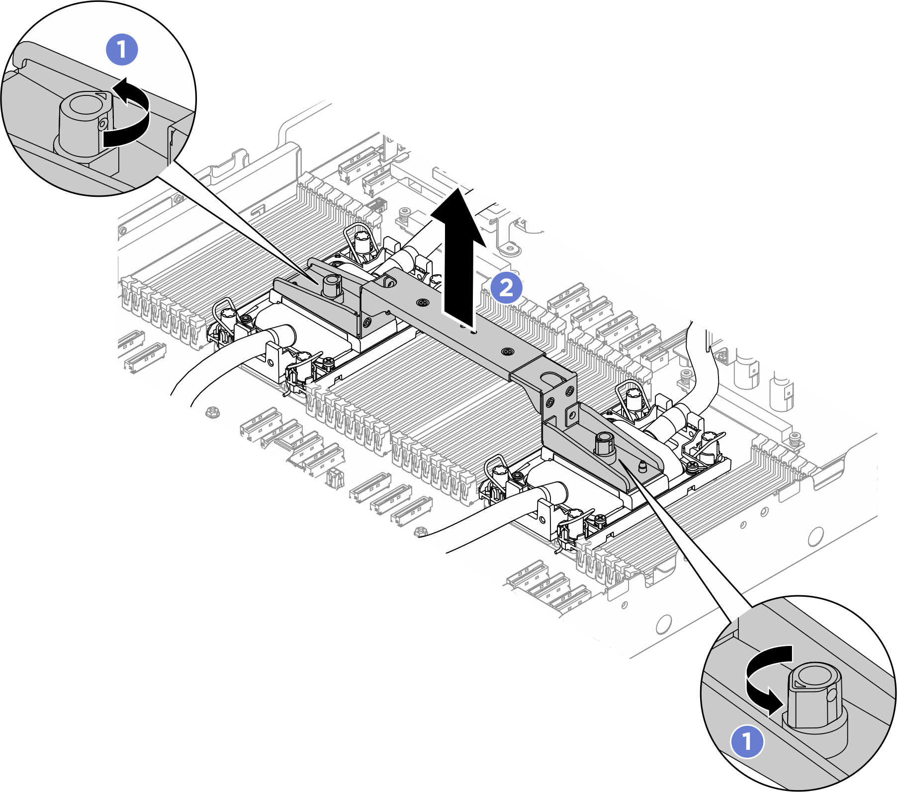 NoteA new
Processor Neptune® Core Module comes with a handle. To replace an old Processor Neptune® Core Module with a new one, remove the handle of the new one as illustrated above.
To replace processors without changing the Processor Neptune® Core Module, a handle is not needed. Skip this step and proceed with further installation.
- Install the cold plate covers. Press the cover down as illustrated.Figure 7. Installing cold plate covers
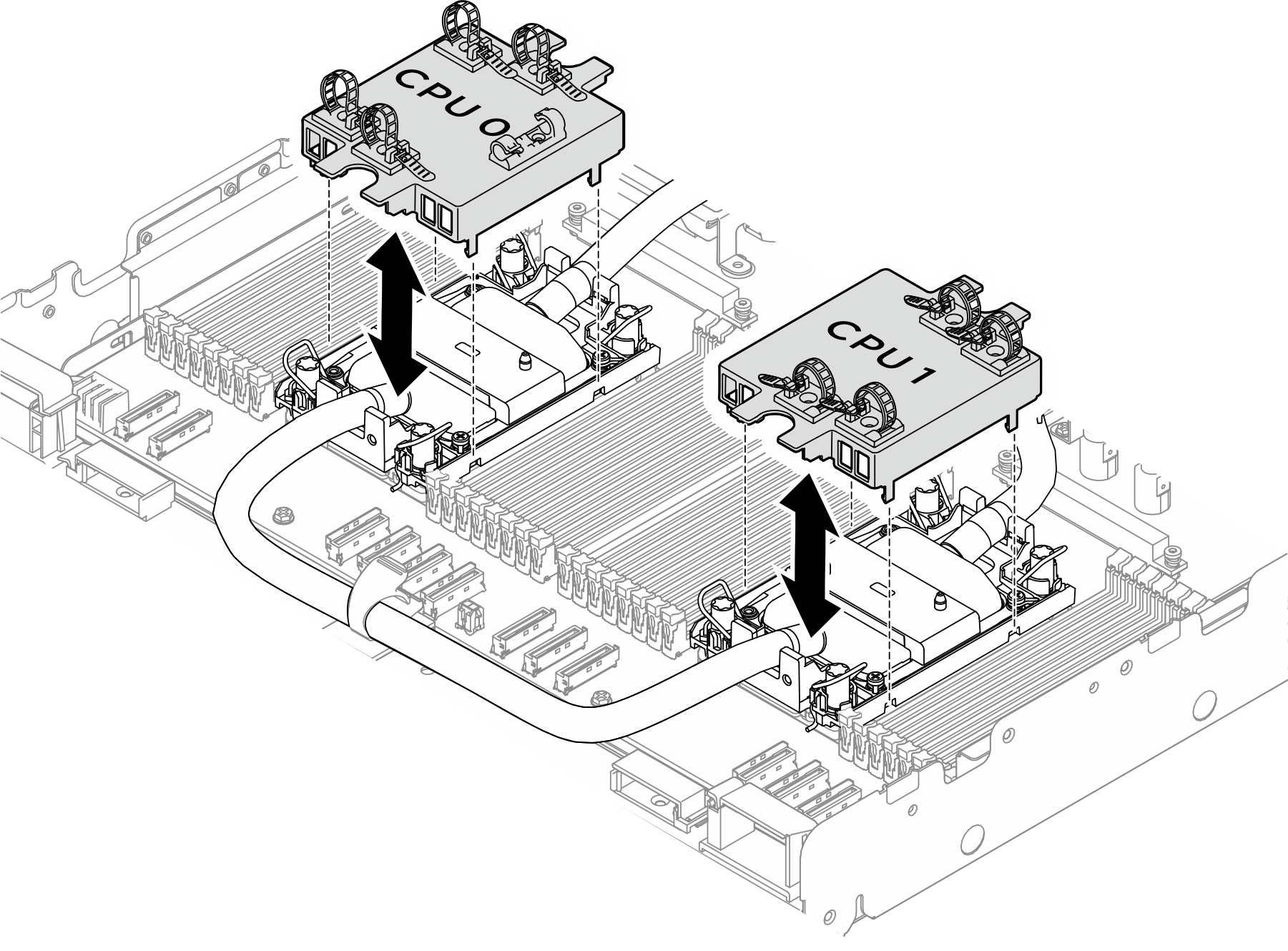 Note
Note- Ensure the cold plate cover matches the corresponding CPU number.
- Install the memory modules that were removed to their original slots.
- Install the hoses.
- Install the hoses to the hose clips and holders.Figure 8. Installing the hoses and module
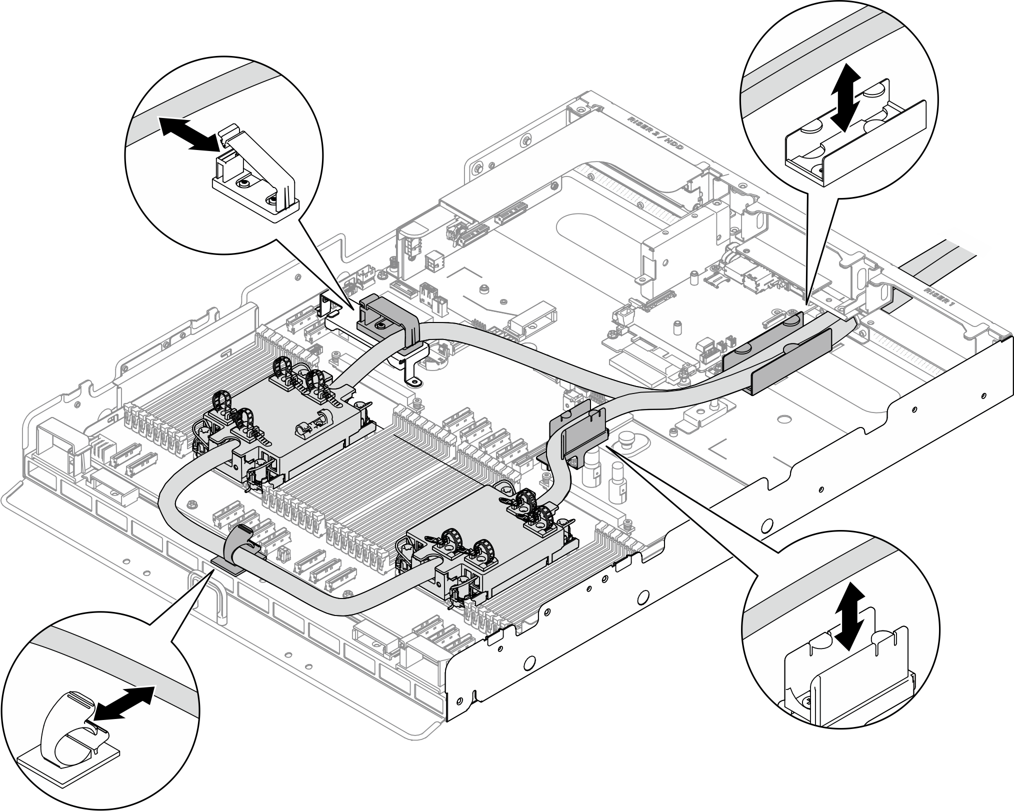 Note
NoteFor leakage sensor module working status, see Leakage sensor module LED.
- Install the first hose through the hose opening on the chassis as illustrated.Figure 9. Installing the hose
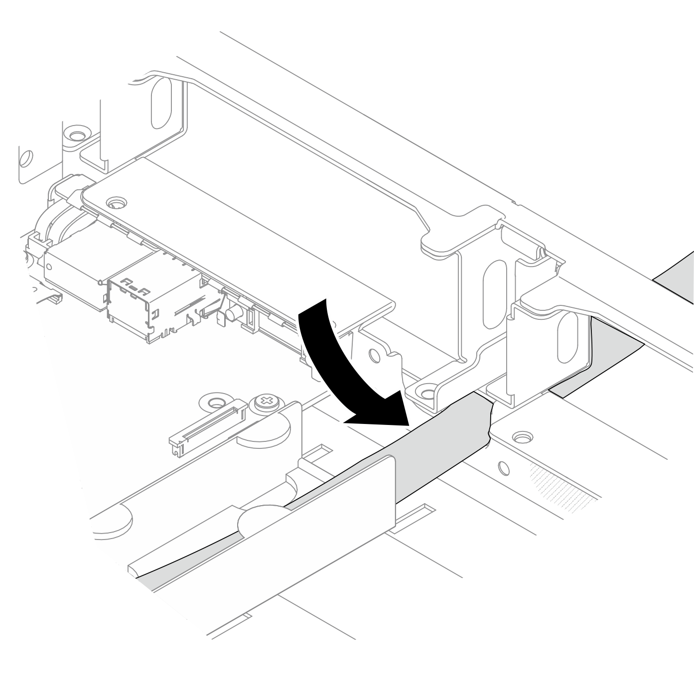
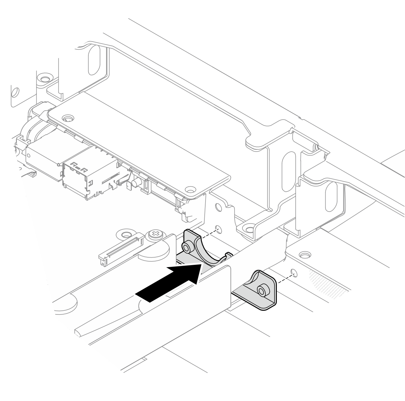
- Place the hose holder under the first hose; then, install the hose holder into position by sliding it towards the hose opening on the chassis.Figure 10. Installing the hose holder
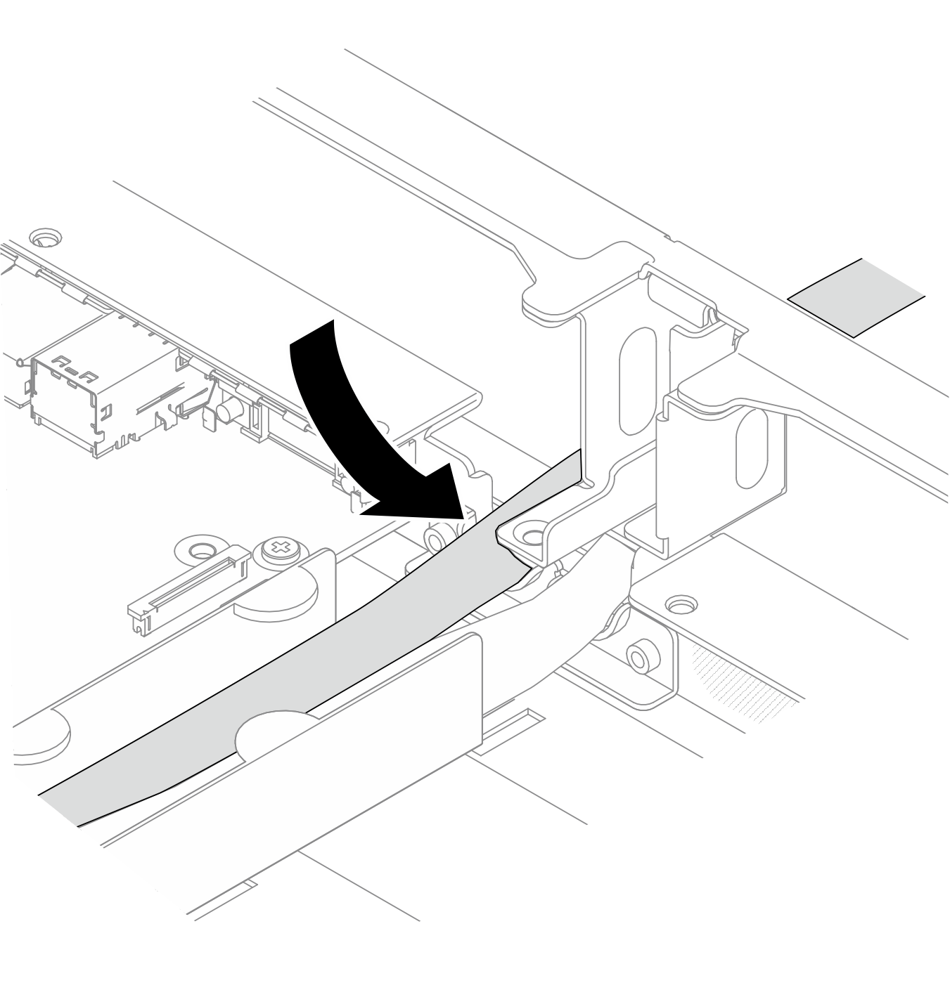
- Install the second hose through the hose opening on the chassis as illustrated.Figure 11. Installing the hose
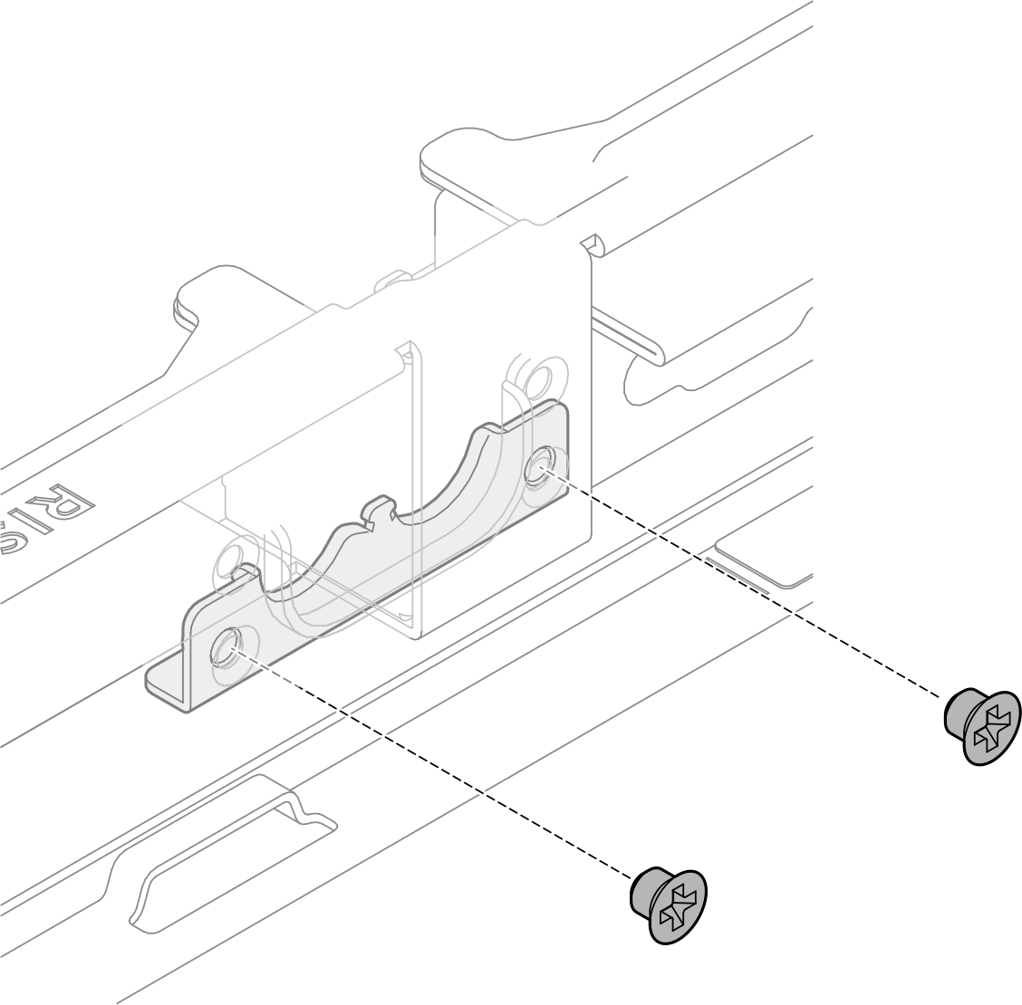
- Fasten the two M3 screws (PH2, 2 x M3, 0.5 newton-meters, 4.3 inch-pounds) to secure the hose holder in place.Figure 12. Securing the hose holder
- Install the hose cover.
- Install the hose cover by placing it on top of the hoses; then, slide it towards the hose opening until it is in place.
- Fasten the three M3 screws (PH2, 3 x M3, 0.5 newton-meters, 4.3 inch-pounds) to secure the hose cover to the chassis.
Figure 13. Installing the hose cover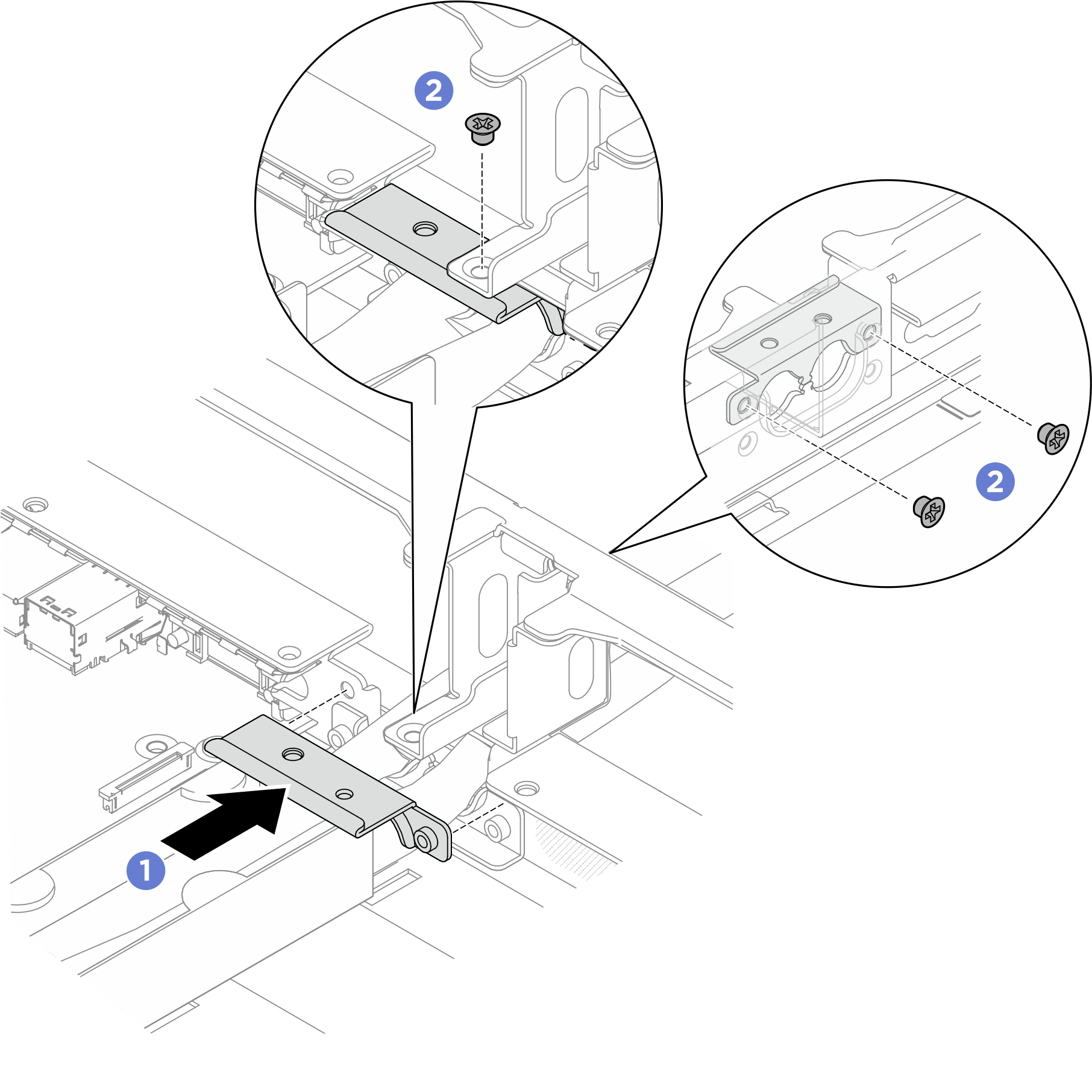
- Install the leakage sensor module bracket. Refer to Install the leakage sensor module bracket for leakage sensor module bracket installation with different configurations.
- Align the leakage sensor module bracket to the slot on the chassis; then, insert the bracket into the slot.
- Fasten the four M3 screws (PH2, 4 x M3, 0.5 newton-meters, 4.3 inch-pounds) to secure the leakage sensor module bracket to the chassis.
Figure 14. Installing the leakage sensor module bracket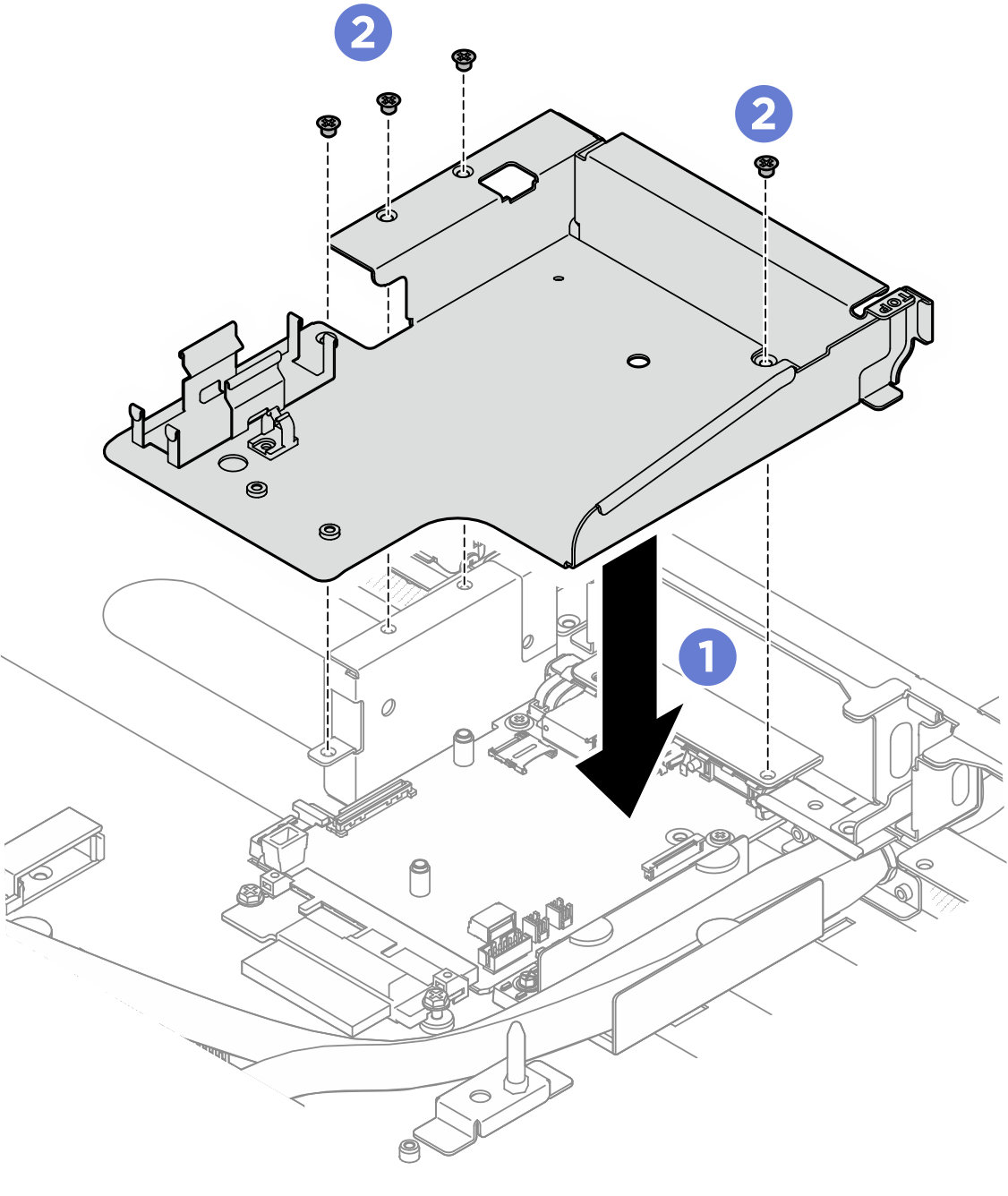
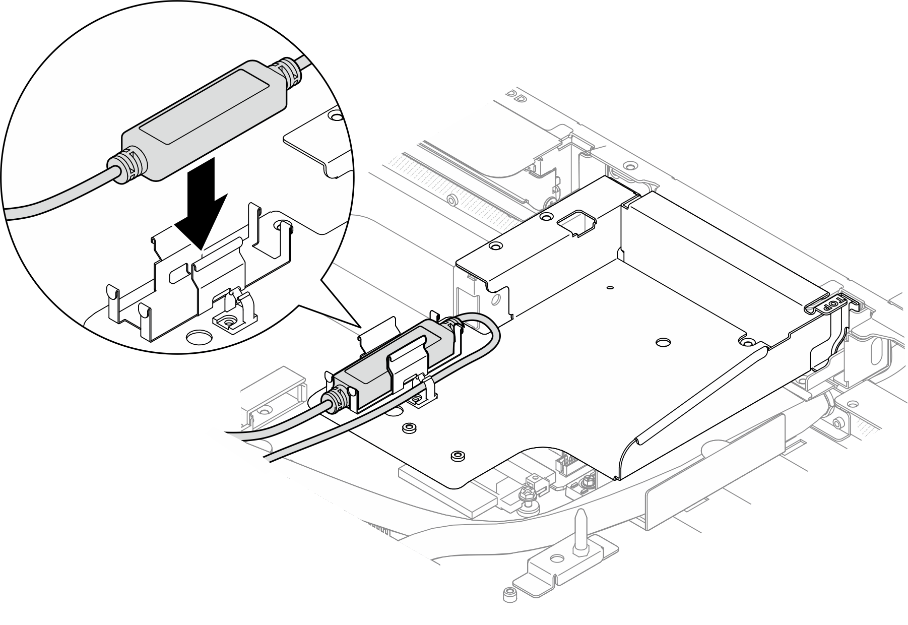
- Install the leakage sensor module to the sensor module holder.Figure 15. Installing the leakage sensor module
After you finish
- Connect the cable of the leakage sensor module to the connector on the system board. See Leakage sensor module cable routing.
- Connect the PCIe switch board signal cables. See PCIe switch board cable routing.
- Connect the front I/O cables. See Front I/O module and integrated diagnostics panel cable routing.
- Reinstall the processor air baffle. See Install the processor air baffle.
- If applicable, reinstall the PCIe riser assembly(ies). See Install a PCIe riser assembly.
- If applicable, reinstall the rear drive cage. See Install the rear drive cage.
- Reinstall the front top cover. See Install the front top cover.
- Reinstall the rear top cover. See Install the rear top cover.
- Reinstall the server to the rack. See Install the server to rack.
- Install the quick connect plugs to the manifolds. See Install the manifold (in-rack system) or Install the manifold (in-row system).
Complete the parts replacement. See Complete the parts replacement.