Install the rear drive cage
Follow the instructions in this section to install the rear drive cage.
About this task
Attention
- Read Installation Guidelines and Safety inspection checklist to ensure that you work safely.
- Touch the static-protective package that contains the component to any unpainted metal surface on the server; then, remove it from the package and place it on a static-protective surface.
- Power off the server and peripheral devices and disconnect the power cords and all external cables. See Power off the server.
- If the server is installed in a rack, slide the server out on its rack slide rails to gain access to the top cover, or remove the chassis from the rack. See Remove the server from rack.
- Two people and one lifting device on site that can support up to 400 lb (181 kg) are required to perform this procedure. If you do not already have a lifting device available, Lenovo offers the Genie Lift GL-8 material lift that can be purchased at Data Center Solution Configurator. Make sure to include the Foot-release brake and the Load Platform when ordering the Genie Lift GL-8 material lift.
Procedure
- Install the rear drive cage support bracket.
 Align the rear drive cage support bracket with the rear drive cage slot on the chassis; then, insert the bracket until it is in place.
 Fasten the six M3 screws (PH2, 6 x M3, 0.5 newton-meters, 4.3 inch-pounds) to secure the rear drive cage support bracket in place.Figure 1. Installing the rear drive cage bracket
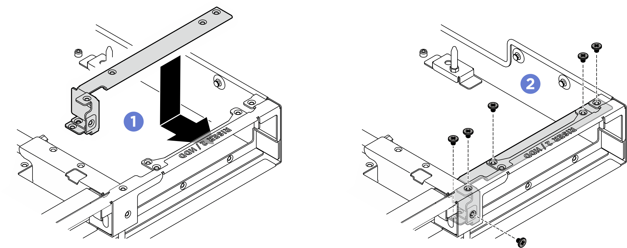
- Align the leakage sensor module bracket to the slot; then, insert the bracket into the slot until it is securely seated. Fasten the two M3 screws (PH2, 2 x M3, 0.5 newton-meters, 4.3 inch-pounds) to secure it in place.
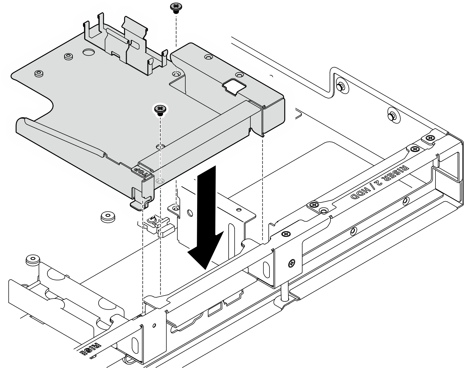 Figure 2. Installing the leakage sensor module bracket (with riser 3)
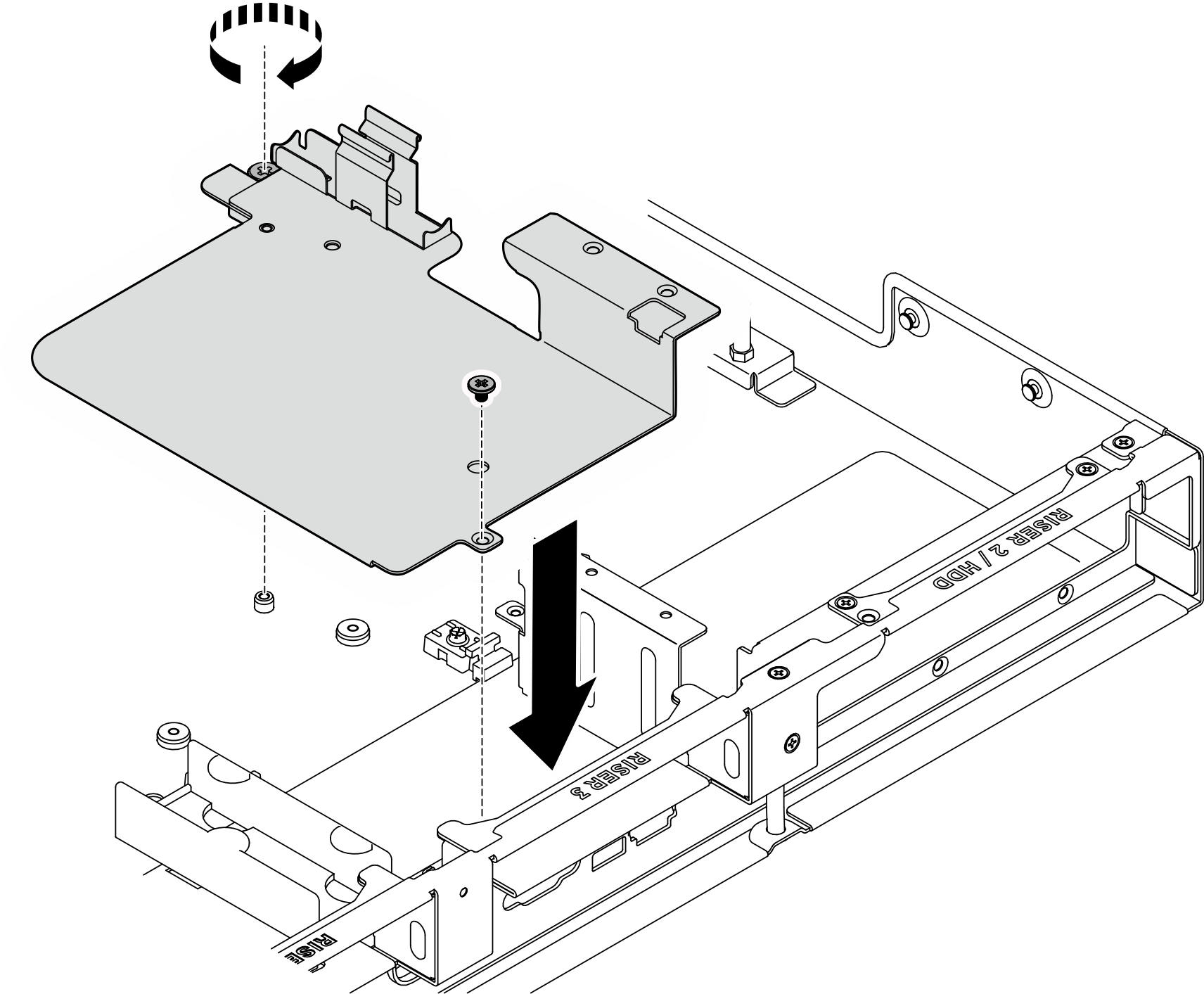
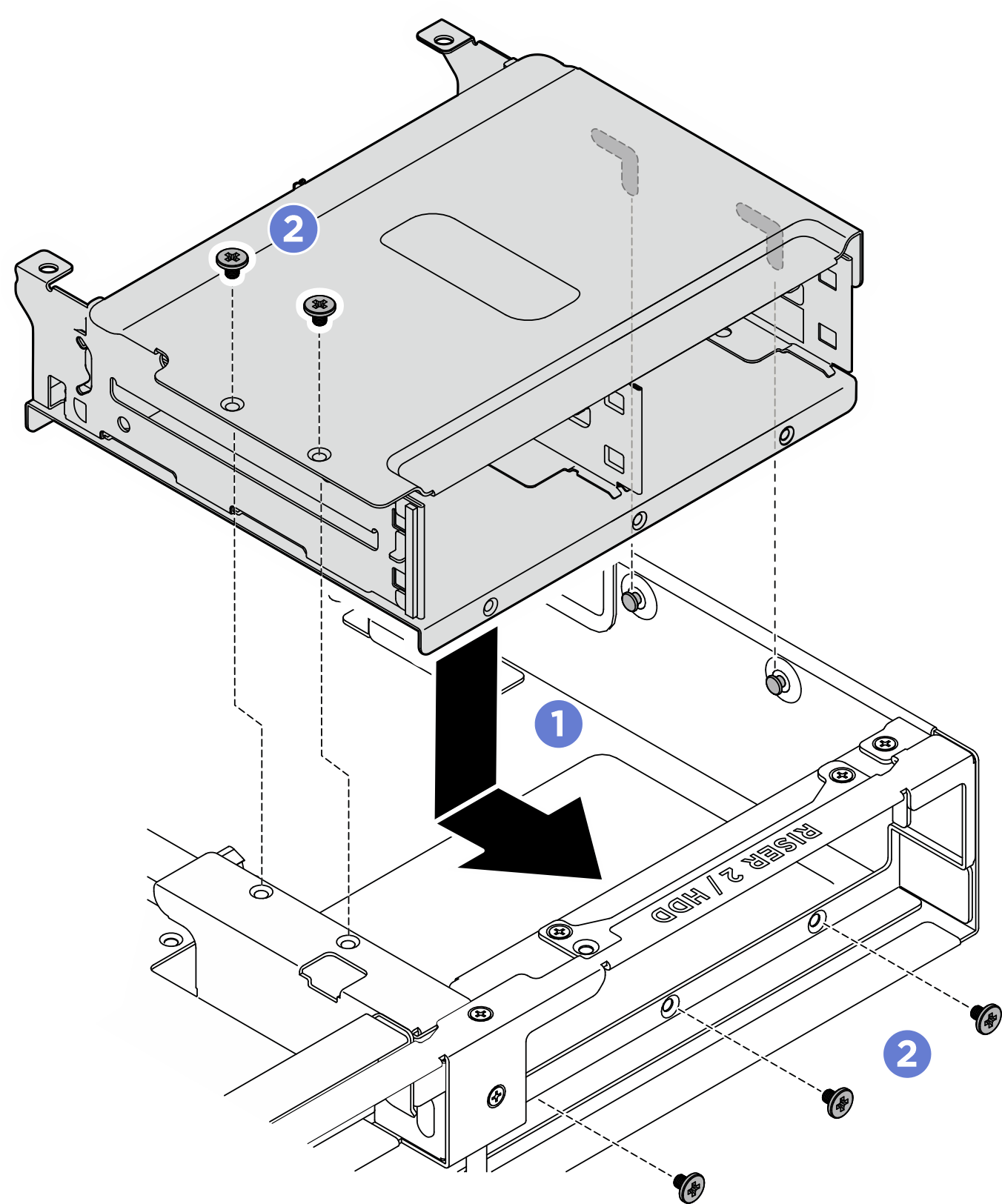
- Align the keyholes on the rear drive cage with the two pins on the chassis; then, lower and insert the rear drive cage into the drive cage slot. Fasten the five M3 screws (PH2, 5 x M3, 0.5 newton-meters, 4.3 inch-pounds) to secure it in place.Figure 3. Installing the rear drive cage
After you finish
- Reinstall the rear 2.5-inch drive backplane. See Install a rear 2.5-inch drive backplane.
- Reinstall all the 2.5-inch hot-swap drives or drive bay fillers (if any) into the rear drive bay. See Install a 2.5-inch hot-swap drive.
- Reinstall the processor air baffle. See Install the processor air baffle.
- Reinstall the rear top cover. See Install the rear top cover.
- Reinstall the front top cover. See Install the front top cover.
- Complete the parts replacement. See Complete the parts replacement.
Give documentation feedback