Install a rear 2.5-inch drive backplane
Follow instructions in this section to install a 2.5-inch drive backplane. The procedure must be executed by a trained technician.
About this task
Attention
- Read Installation Guidelines and Safety inspection checklist to ensure that you work safely.
- Touch the static-protective package that contains the component to any unpainted metal surface on the server; then, remove it from the package and place it on a static-protective surface.
- Power off the server and peripheral devices and disconnect the power cords and all external cables. See Power off the server.
- If the server is installed in a rack, slide the server out on its rack slide rails to gain access to the top cover, or remove the chassis from the rack. See Remove the server from rack.
- Two people and one lifting device on site that can support up to 400 lb (181 kg) are required to perform this procedure. If you do not already have a lifting device available, Lenovo offers the Genie Lift GL-8 material lift that can be purchased at Data Center Solution Configurator. Make sure to include the Foot-release brake and the Load Platform when ordering the Genie Lift GL-8 material lift.
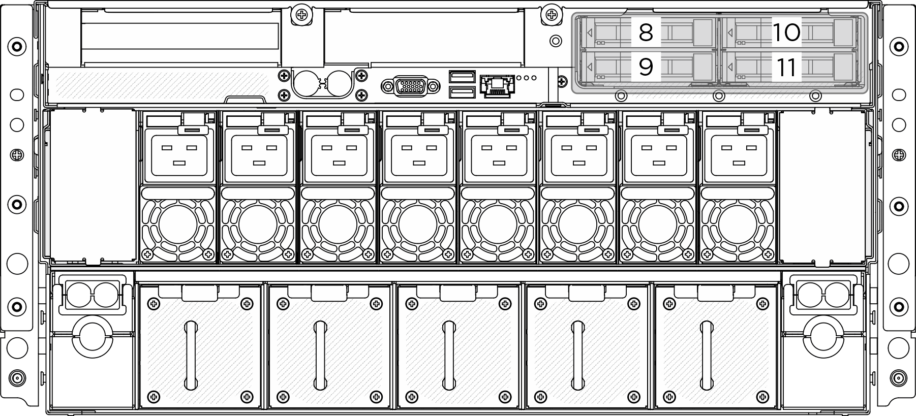
- The server supports one rear 2.5-inch drive backplane with the following corresponding drive backplane numbering.Figure 1. Rear 2.5-inch drive backplane numbering
- Install air baffle to the rear drive backplane when NVIDIA BlueField-3 B3220 is installed.
Firmware and driver download: You might need to update the firmware or driver after replacing a component.
Go to Drivers and Software download website for ThinkSystem SR780a V3 to see the latest firmware and driver updates for your server.
Go to Update the firmware for more information on firmware updating tools.
Procedure
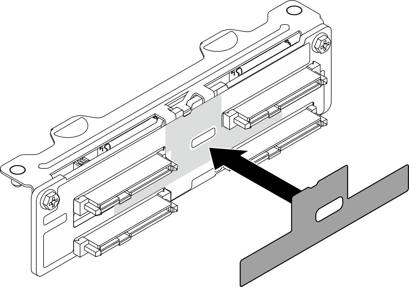
- Install air baffle to the rear drive backplane when NVIDIA BlueField-3 B3220 is installed. Remove the liner from the air baffle; then, align and stick the air baffle to the backplane.Figure 2. Rear drive backplane air baffle installation
 Align the 2.5-inch drive backplane with the screw holes on the bracket; then, fasten the two M3 screws (PH2, 2 x M3, 0.5 newton-meters, 4.3 inch-pounds) to secure the drive backplane to the bracket.Figure 3. Rear 2.5-inch drive backplane installation
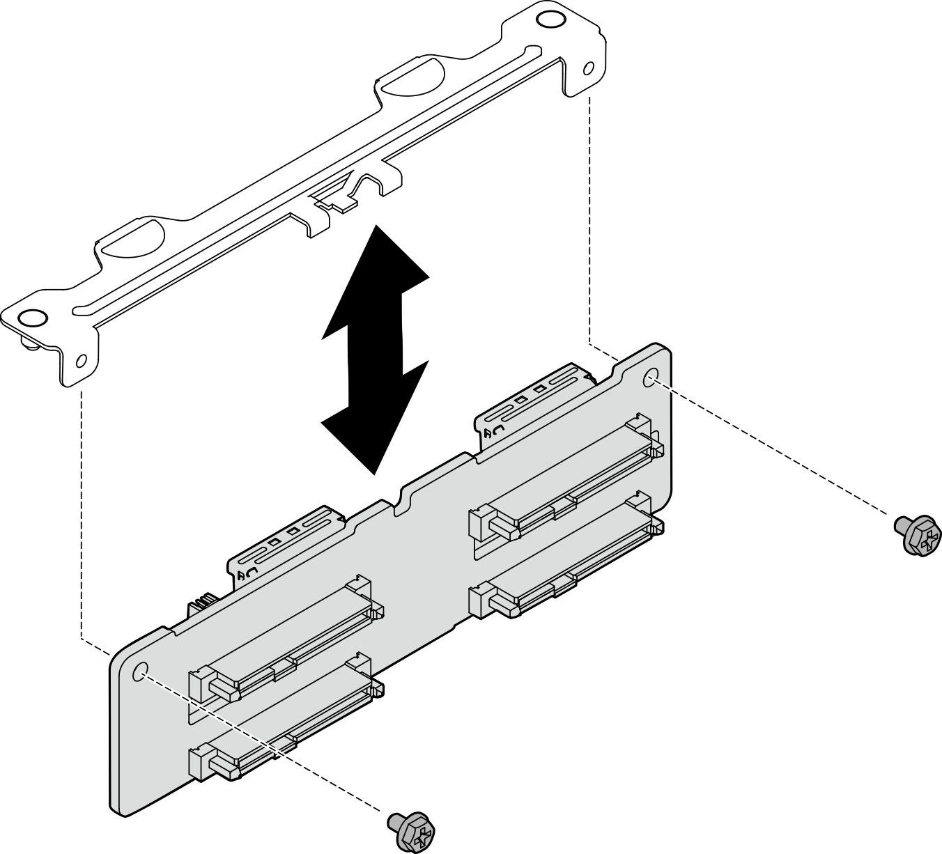
 Align the pins on the backplane bracket with the slot on the rear drive cage; then, lower the backplane into the drive cage so that the pins of the backplane pass through the holes on the drive cage, and press the backplane into position.Figure 4. Rear 2.5-inch drive backplane bracket installation
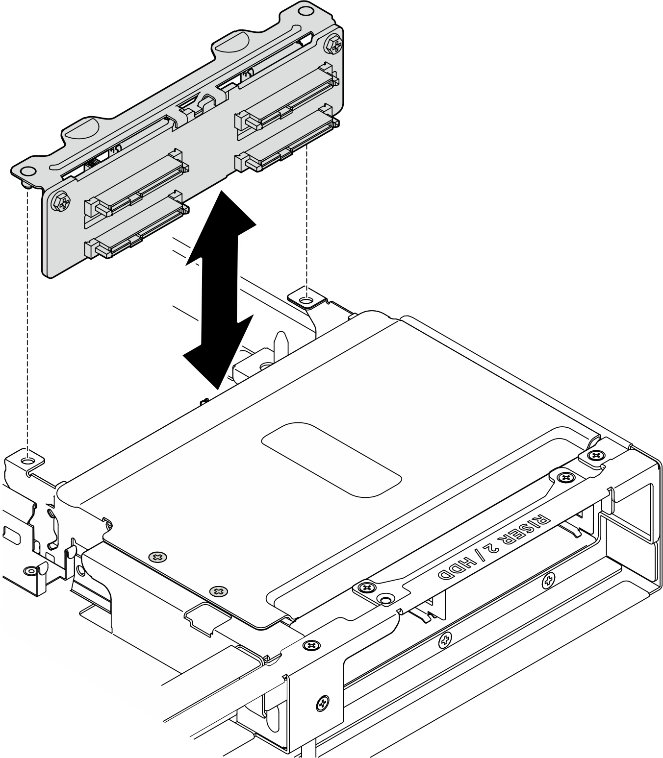
- If necessary, attach the labels to both ends of the cable.
- Attach the white space portion of the label to one end of the cable.
- Wrap the label around the cable and attach it to the white space portion.
- Repeat to attach the other label to the opposite end of the cable.
Figure 5. Label application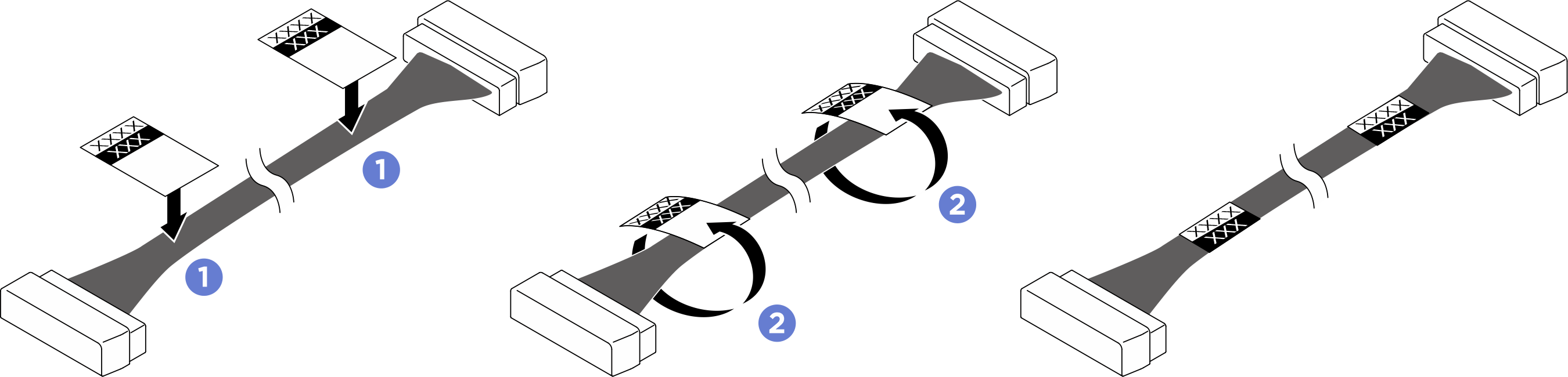 NoteSee the table below to identify the corresponding labels for the cable.
Cable From To Label 1 Backplane 1: NVMe connector 2-3 System board: MCIO connector 4B (MCIO4B) - R-NVME 2-3
- MCIO 4B
2 Backplane 2: Power connector System board: Backplane power connector (BP PWR/SIG 2) - R-BP PWR
- SIG 2
3 Backplane 2: NVMe connector 0-1 System board: MCIO connector 4A (MCIO4A) - R-NVME 0-1
- MCIO 4A
After you finish
- Reinstall all the 2.5-inch hot-swap drives or drive bay fillers (if any) into the drive bay. See Install a 2.5-inch hot-swap drive.
- Reinstall the processor air baffle. See Install the processor air baffle.
- Reinstall the rear top cover. See Install the rear top cover.
- Reinstall the front top cover. See Install the front top cover.
- Complete the parts replacement. See Complete the parts replacement.
Give documentation feedback