Remove the rear drive cage
Follow the instructions in this section to remove the rear drive cage. (trained technician only)
Attention
- Read Installation Guidelines and Safety inspection checklist to ensure that you work safely.
- Touch the static-protective package that contains the component to any unpainted metal surface on the server; then, remove it from the package and place it on a static-protective surface.
- Power off the server and peripheral devices and disconnect the power cords and all external cables. See Power off the server.
- If the server is installed in a rack, slide the server out on its rack slide rails to gain access to the top cover, or remove the chassis from the rack. See Remove the server from rack.
- Two people and one lifting device on site that can support up to 400 lb (181 kg) are required to perform this procedure. If you do not already have a lifting device available, Lenovo offers the Genie Lift GL-8 material lift that can be purchased at Data Center Solution Configurator. Make sure to include the Foot-release brake and the Load Platform when ordering the Genie Lift GL-8 material lift.
Procedure
- Make preparation for this task.
- Remove the front top cover. See Remove the front top cover.
- Remove the rear top cover. See Remove the rear top cover.
- Remove all the 2.5-inch hot-swap drives and the drive bay fillers (if any) from the rear drive bay. See Remove a 2.5-inch hot-swap drive.
- Remove the processor air baffle. See Remove the processor air baffle.
- Remove the rear 2.5-inch drive backplane. See Remove a rear 2.5-inch drive backplane.
- Remove the rear drive cage.
 Unfasten the five M3 screws; then, slide the drive cage towards the front of the chassis to disengage it from the pins on the chassis. Grasp the drive cage and remove it from the chassis.Figure 1. Removing the rear drive cage
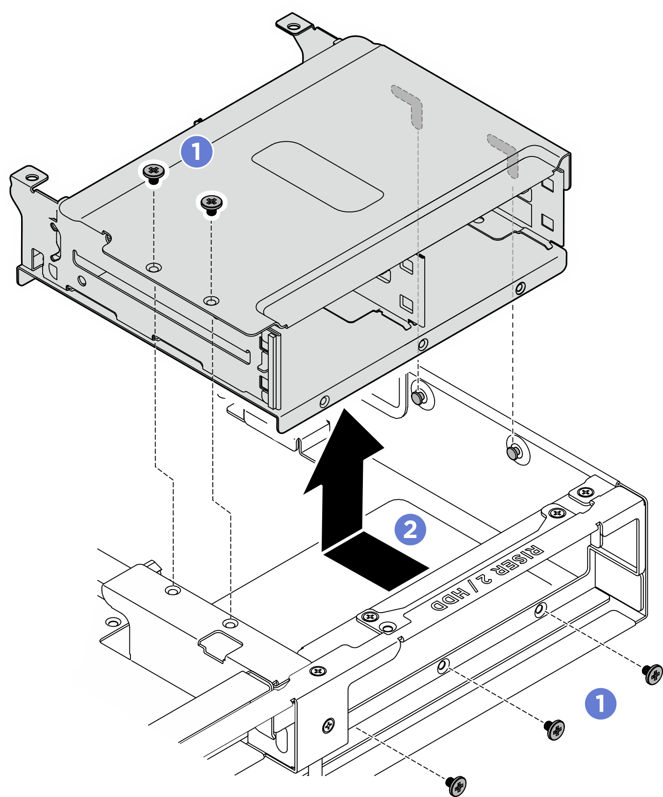
- Remove the rear drive cage support bracket if necessary.
 Unfasten the two M3 screws that secure the leakage sensor module bracket to the chassis; then, remove it from the chassis.Figure 2. Removing the leakage sensor module bracket
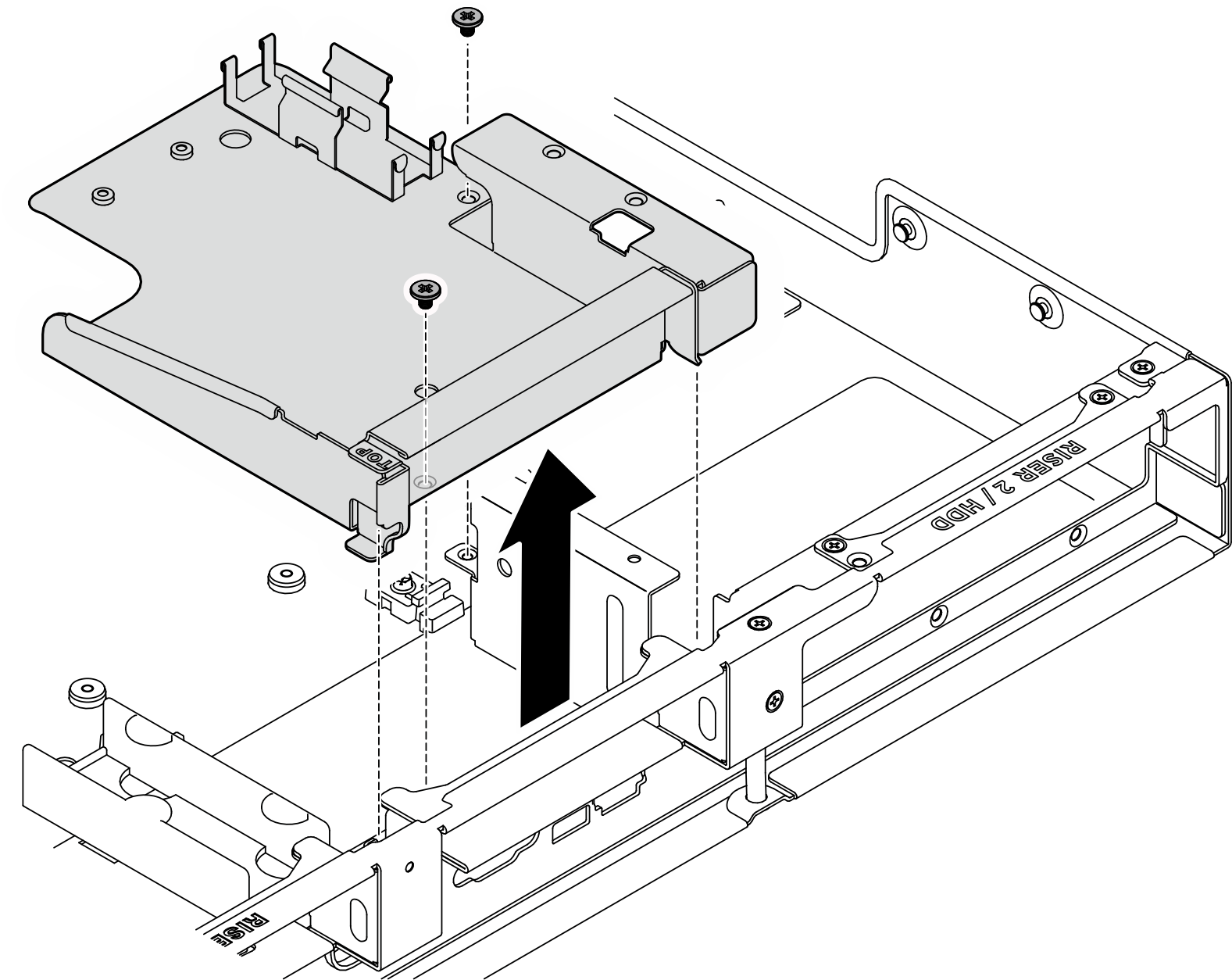 Figure 3. Removing the leakage sensor module bracket (with riser 3)
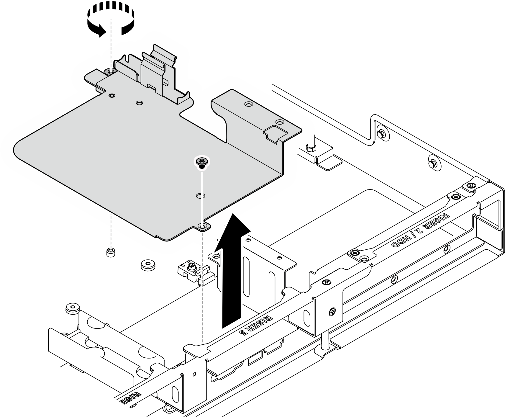
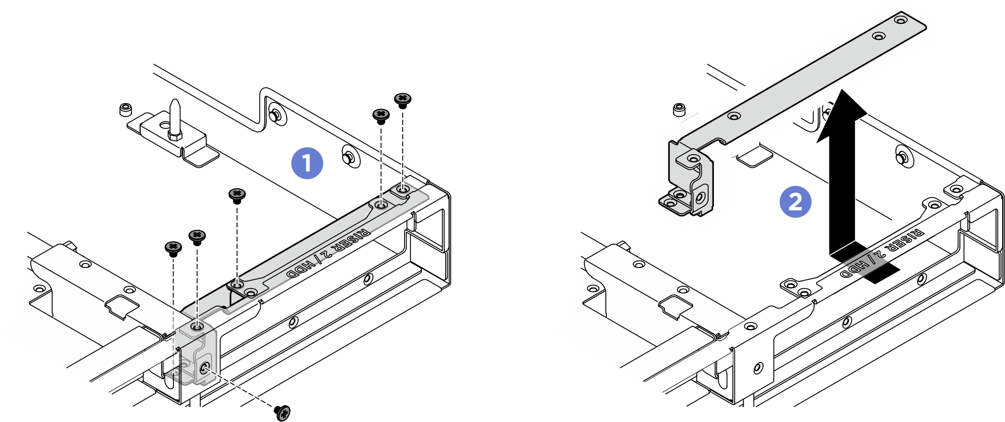
- Unfasten the six M3 screw that secure the rear drive cage support bracket to the chassis.
- Grasp the rear drive cage support bracket to remove it from the chassis.Figure 4. Removing the rear drive cage support bracket
After you finish
- Install a replacement. See Install the rear drive cage.
- Complete the parts replacement. See Complete the parts replacement.
Give documentation feedback