Remove the server from rack
Follow instructions in this section to remove the server from the rack.
S037
CAUTION
The weight of this part or unit is more than 55 kg (121.2 lb). It takes specially trained persons, a lifting device, or both to safely lift this part or unit.
S036
CAUTION
Use safe practices when lifting.
R006
CAUTION
Do not place any object on top of a rack-mounted device unless that rack-mounted device is intended for use as a shelf.
About this task
Attention
Read Installation Guidelines and Safety inspection checklist to ensure that you work safely.
Power off the server and peripheral devices and disconnect the power cords and all external cables. See Power off the server.
- Two people and one lifting device on site that can support up to 400 lb (181 kg) are required to perform this procedure. If you do not already have a lifting device available, Lenovo offers the Genie Lift GL-8 material lift that can be purchased at Data Center Solution Configurator. Make sure to include the Foot-release brake and the Load Platform when ordering the Genie Lift GL-8 material lift.
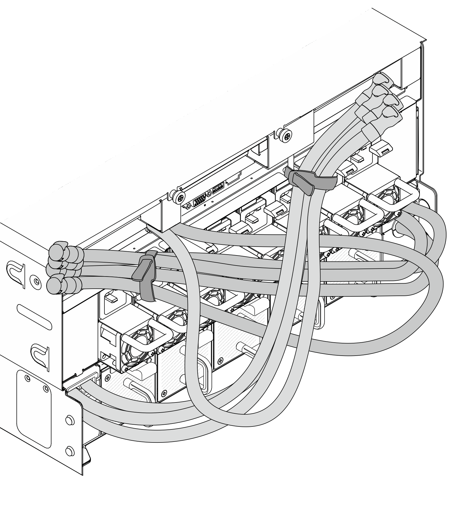
Secure the hoses with the hose ties before removing the server from the rail.
- Make sure a lifting device is available on site to lift the server.S037CAUTIONThe weight of this part or unit is more than 55 kg (121.2 lb). It takes specially trained persons, a lifting device, or both to safely lift this part or unit.
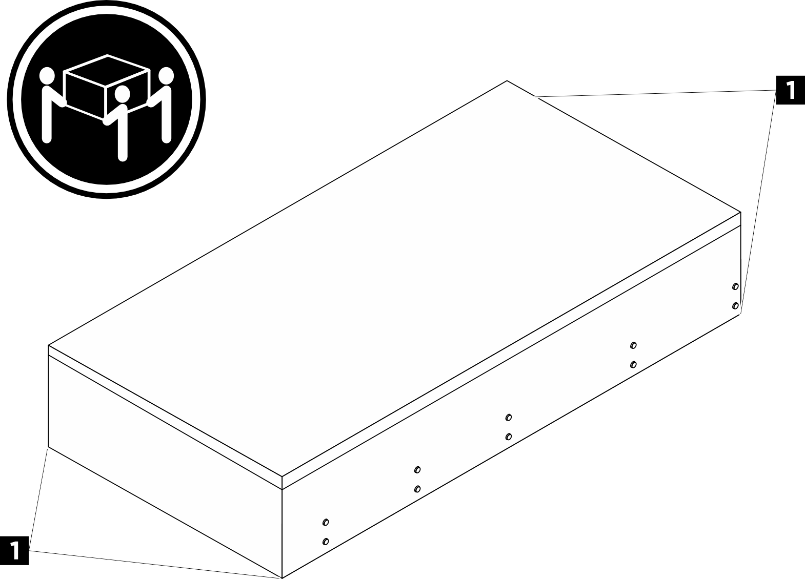 CAUTIONMake sure to lift the server by holding the lift points.
1 Lift point - If the chassis was shipped in the rack cabinet, remove the shipping brackets before powering on the server. Unfasten the four screws and remove the shipping bracket.
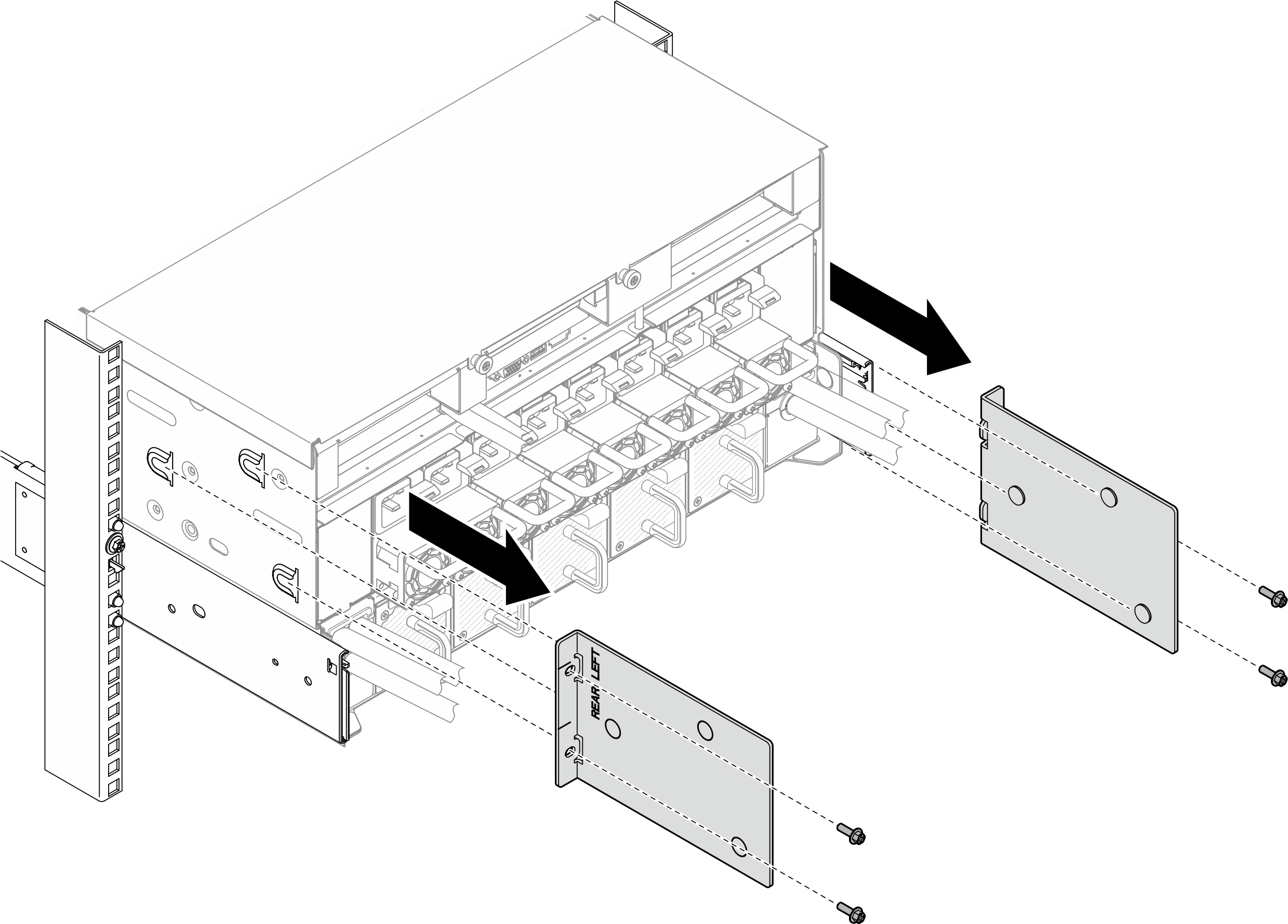
- If the chassis was shipped in the rack cabinet, remove the EIA covers and remove the two M5 screws; then, install the EIA covers back in place.
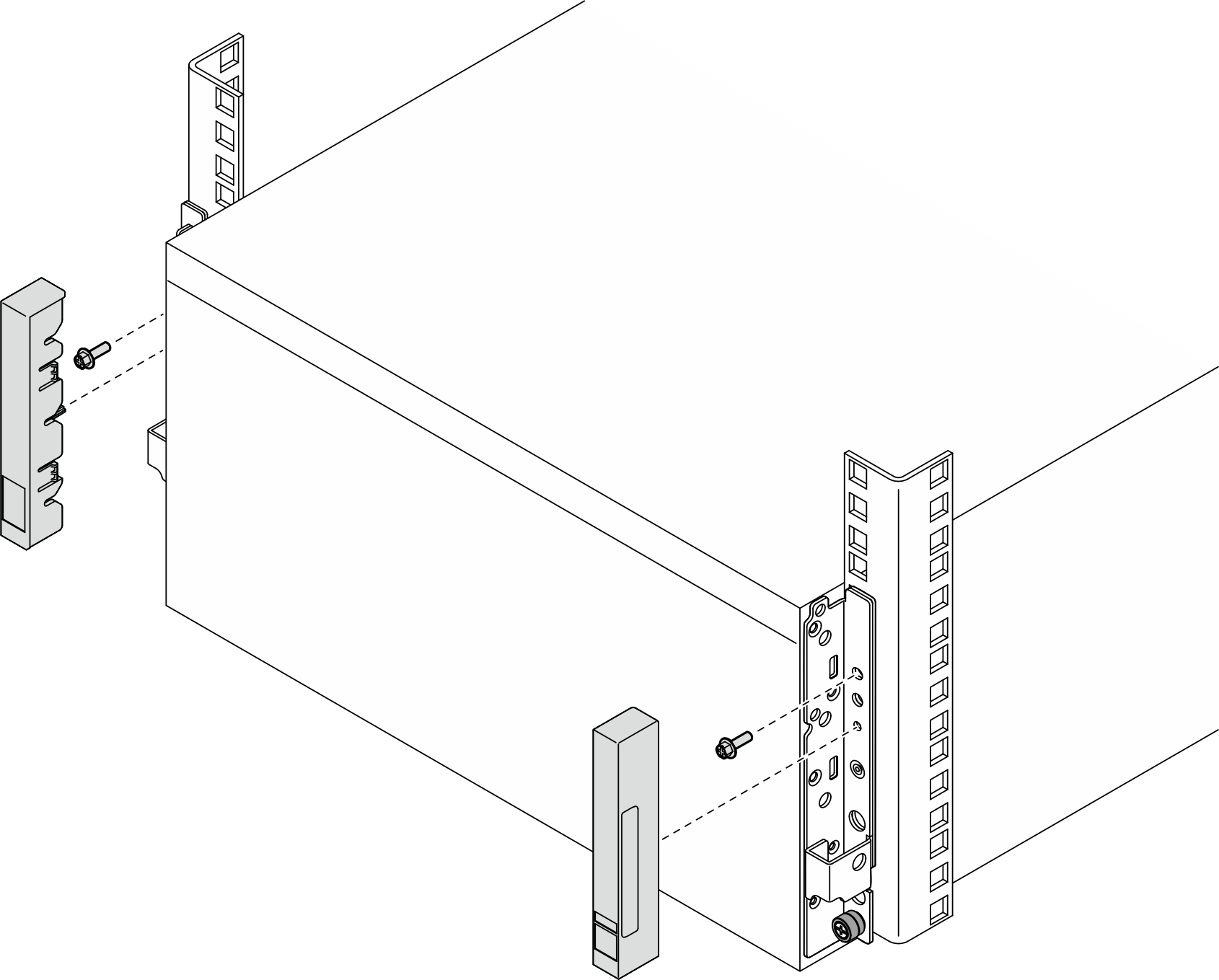
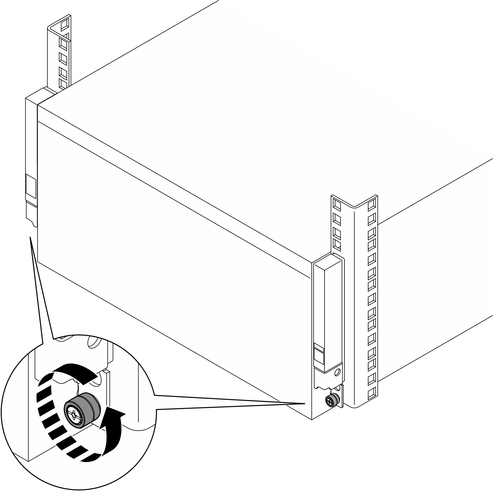
- Loosen the thumbscrews.
- Install the front lift handle.
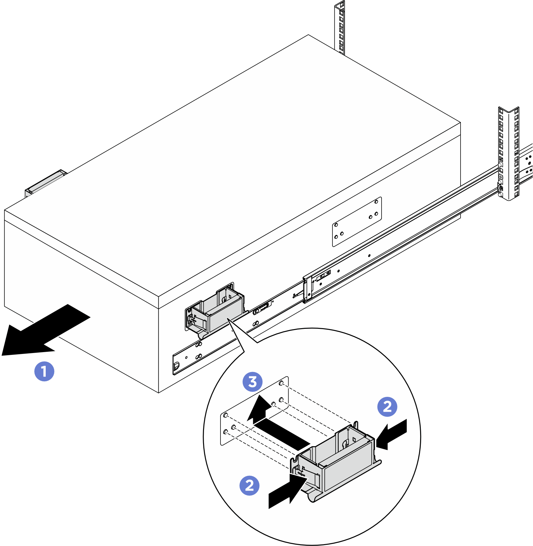
 Slide the server out until it stops.
 Pinch both flaps on the side of the handles.
 Align the handles with the 6 posts on the sides of the server; then slide the handles up to secure them to the server.
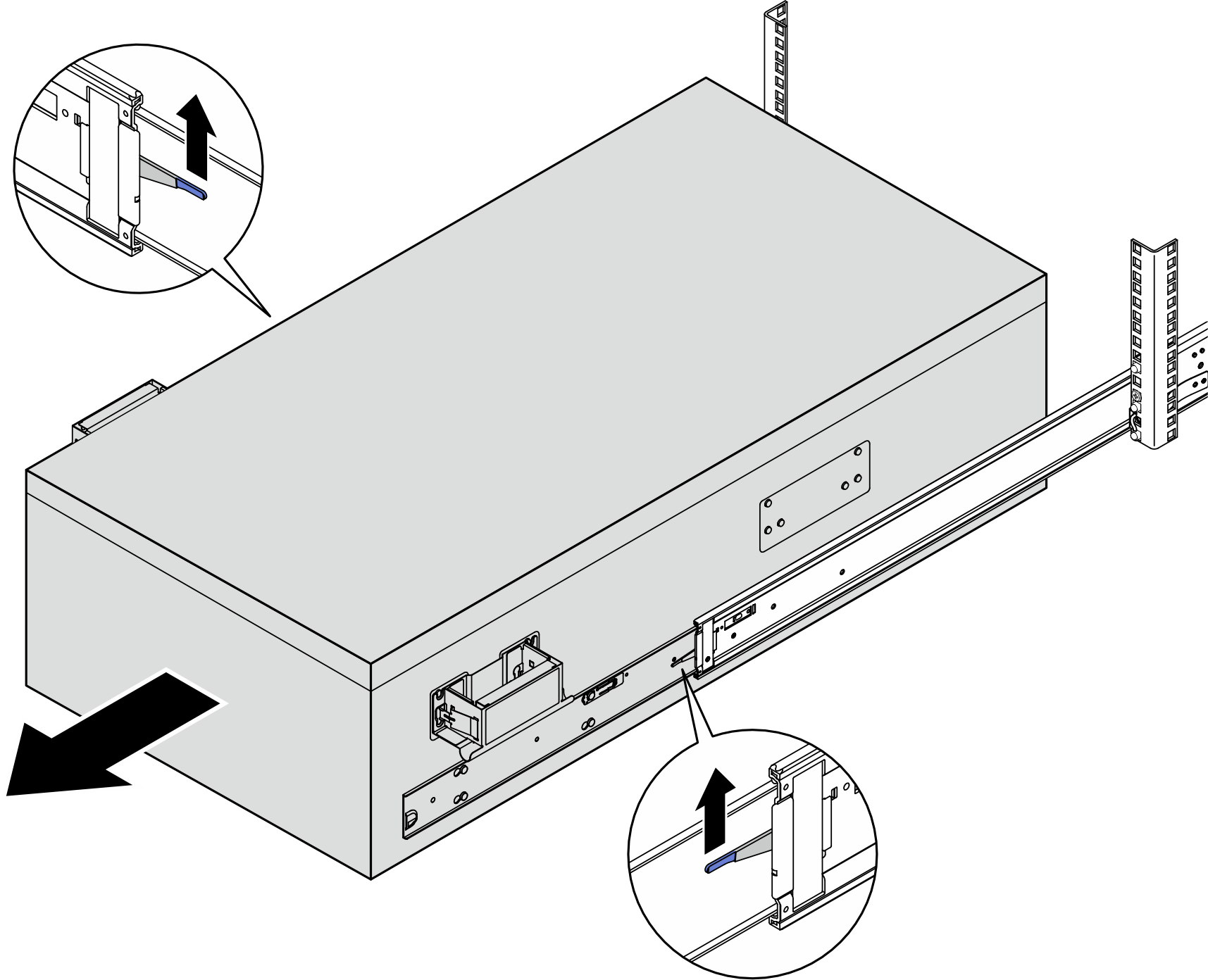
CAUTIONMake sure to install both front lift handles first before proceeding sliding out. - Lift the first lock latches up to proceed sliding out.
- Attach the rear handles.
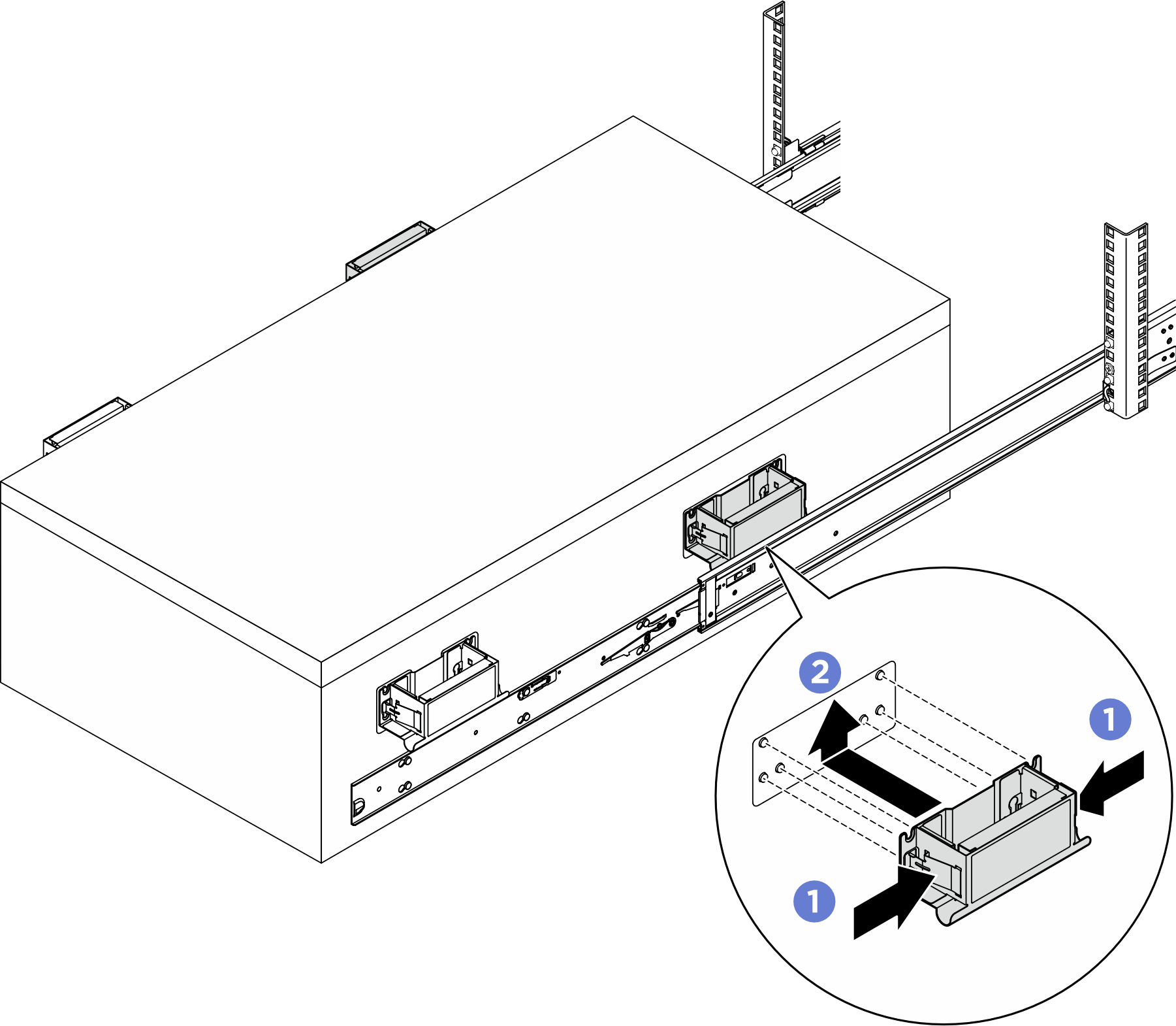
- Pinch both flaps on the side of the handles.
- Align the handles with the 6 posts on the sides of the server; then slide the handles up to secure them to the server.
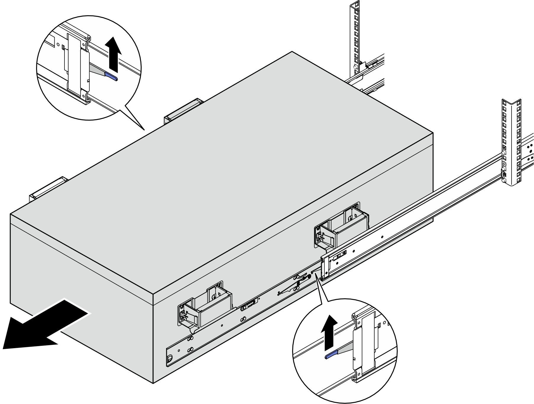
CAUTIONMake sure to install both rear lift handles first before proceeding sliding out. - Lift the second lock latches up and remove the server completely from the rack; then place it on a flat and stable surface.
- Remove the lift handles.
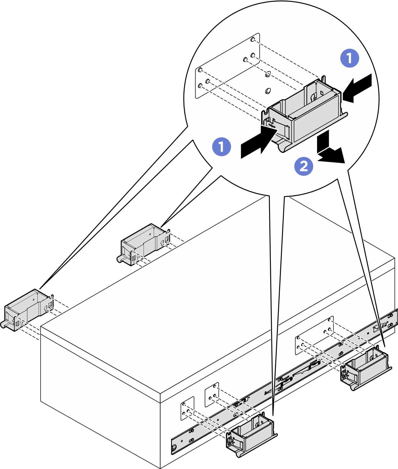
- Pinch both flaps on the side of the handles.
- Slide the handles down to remove them.
NoteMake sure to remove all 4 lift handles. - Loosen and remove an M4 screw in the corresponding hole on both inner rails as shown.
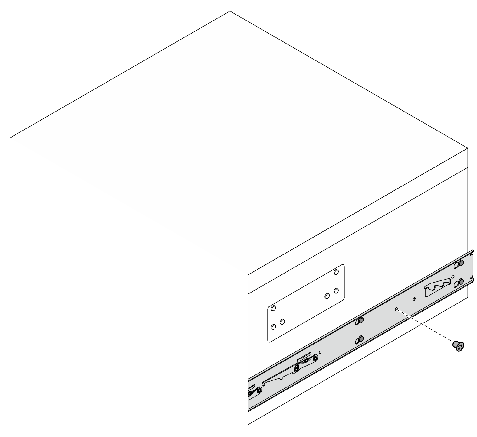
- Remove the inner rail from the server.
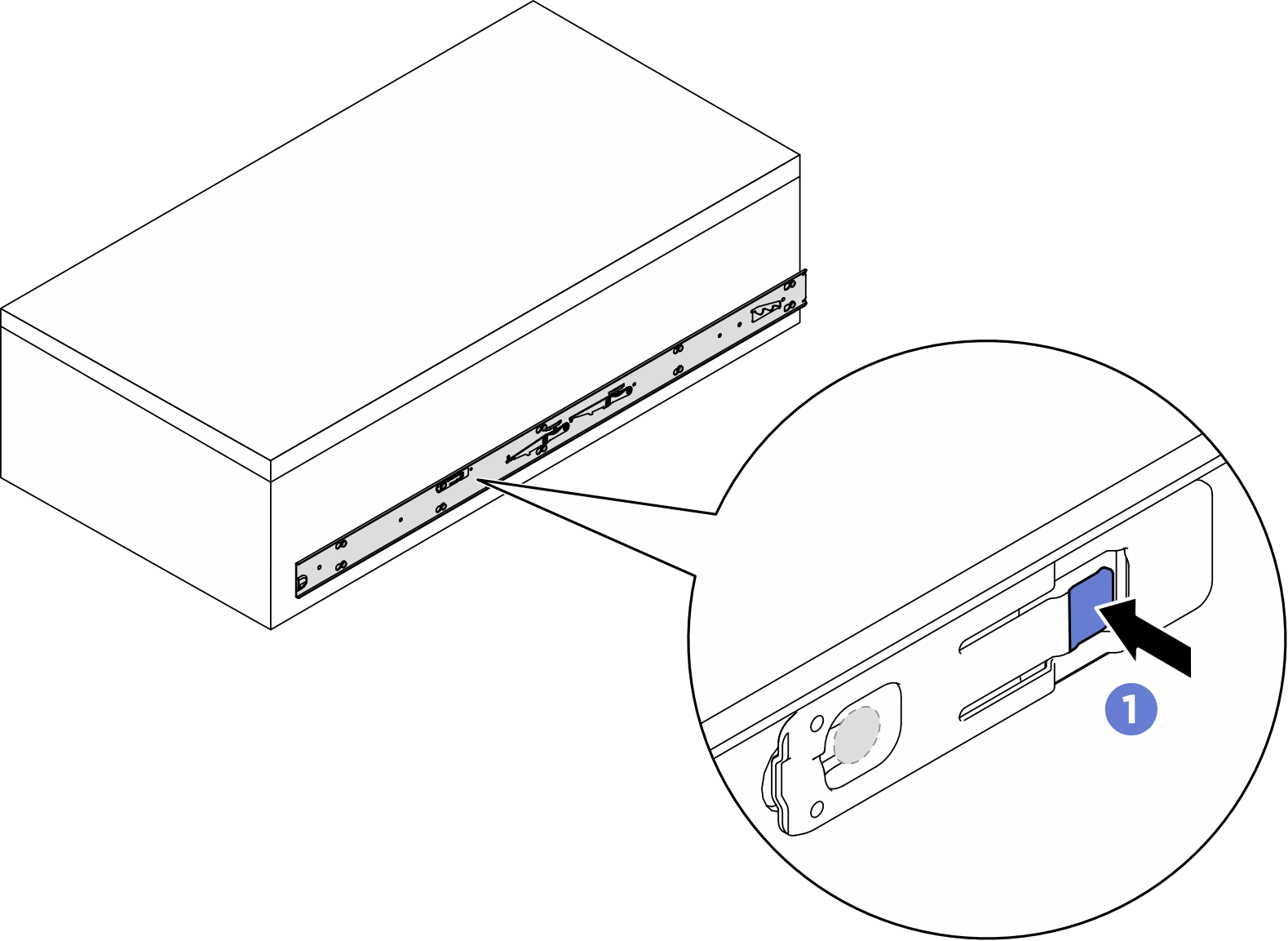
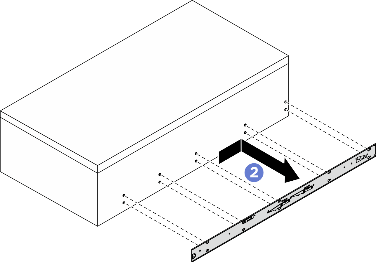
- Press and hold on the release tab; then, simultaneously, slide the inner rail backwards until the T-pins on the server disengage from the inner rail.
- Remove the inner rail from the server.
After you finish
Carefully lay the chassis on a flat, static-protective surface.
- To remove the rails from a rack, follow the instructions that are provided in the Rail installation Guide.
Give documentation feedback