Remove a PCIe riser assembly
Follow instructions in this section to remove a PCIe riser assembly. The procedure must be executed by a trained technician.
About this task
Attention
- Read Installation Guidelines and Safety inspection checklist to ensure that you work safely.
- Power off the server and peripheral devices and disconnect the power cords and all external cables. See Power off the server.
- If the server is installed in a rack, slide the server out on its rack slide rails to gain access to the top cover, or remove the chassis from the rack. See Remove the server from rack.
- Two people and one lifting device on site that can support up to 400 lb (181 kg) are required to perform this procedure. If you do not already have a lifting device available, Lenovo offers the Genie Lift GL-8 material lift that can be purchased at Data Center Solution Configurator. Make sure to include the Foot-release brake and the Load Platform when ordering the Genie Lift GL-8 material lift.
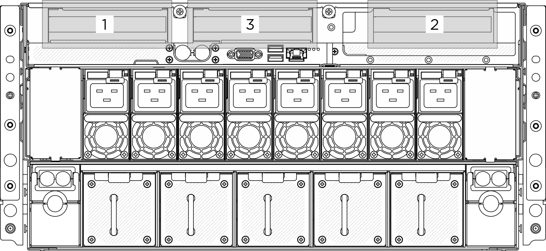
- The server support up to three PCIe risers, see the following illustration for corresponding locations.Figure 1. PCIe riser locations
Note
To maintain proper system cooling, do not operate the server without a PCIe riser or a riser filler installed in the CPU complex.
Procedure
- Make preparation for this task.
- Remove the front top cover. See Remove the front top cover.
- Remove the rear top cover. See Remove the rear top cover.
- Remove the processor air baffle. See Remove the processor air baffle.
- Remove the PCIe riser assembly in riser 1 slot.
 Unfasten the thumbscrew on the PCIe riser.
 Lift the PCIe riser assembly out of the CPU complex.
- Disconnect the PCIe riser assembly cables. See PCIe riser cable routing for more information on the internal cable routing.Figure 2. Removing x16 PCIe riser assembly in riser 1 slot
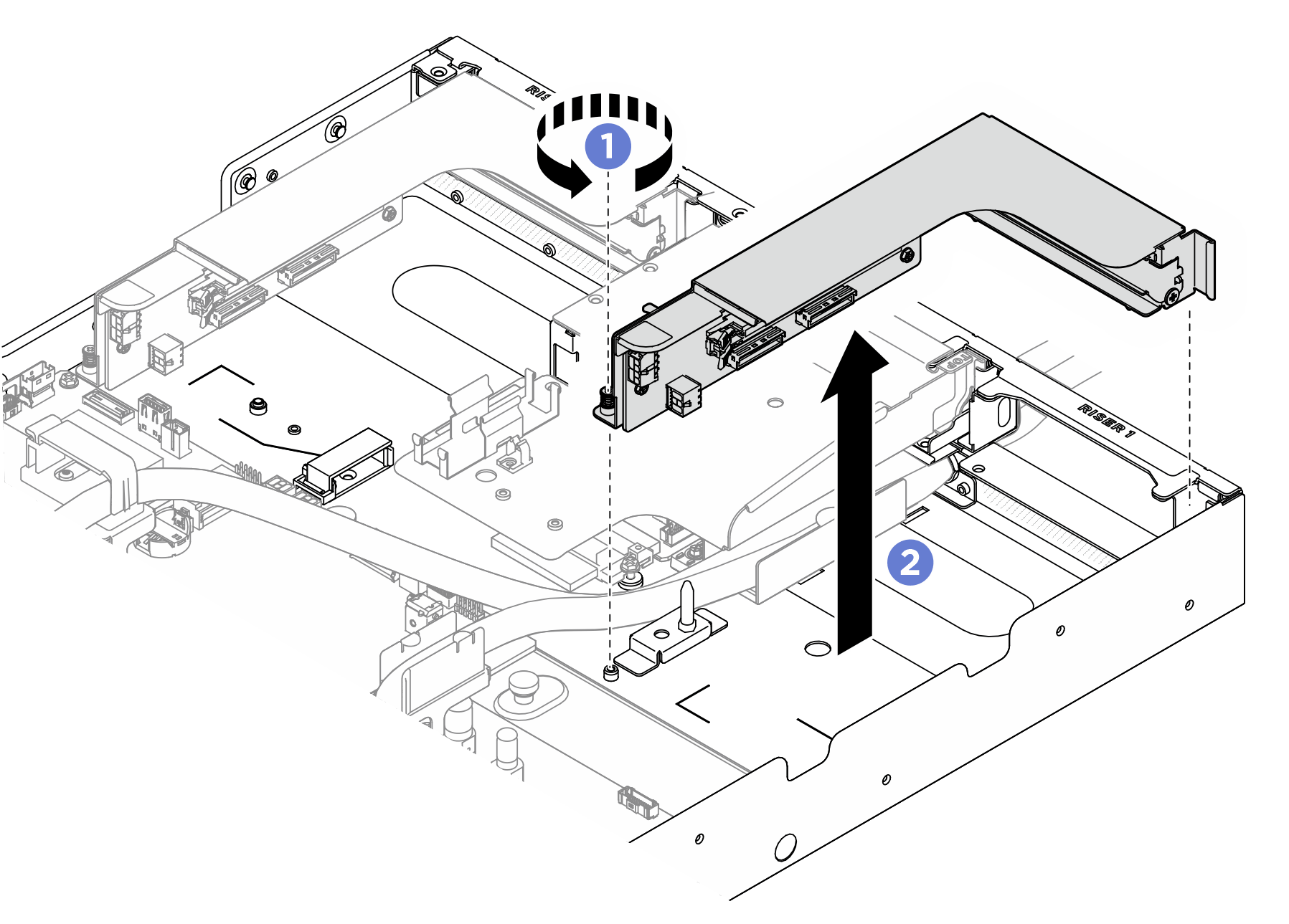 Figure 3. Removing x8 PCIe riser assembly in riser 1 slot
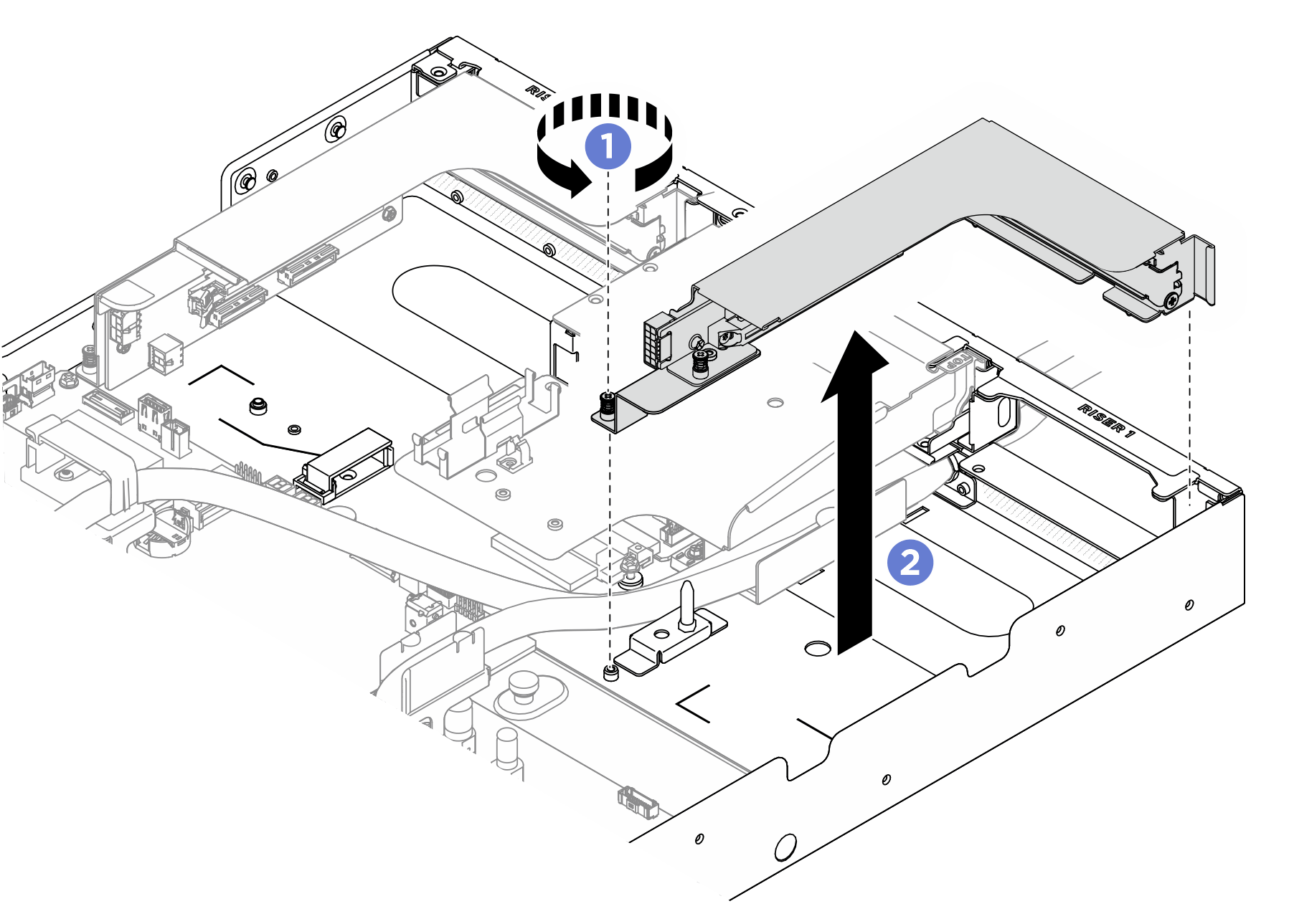
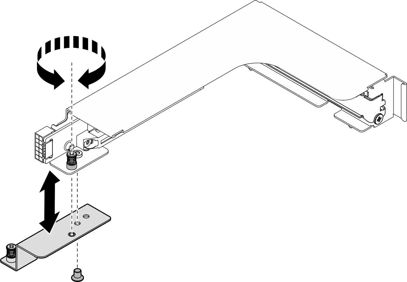
- If necessary, unfasten the captive screw to separate the x8 PCIe riser cage from its adapter bracket.Figure 4. Separating x8 PCIe riser cage and adapter bracket
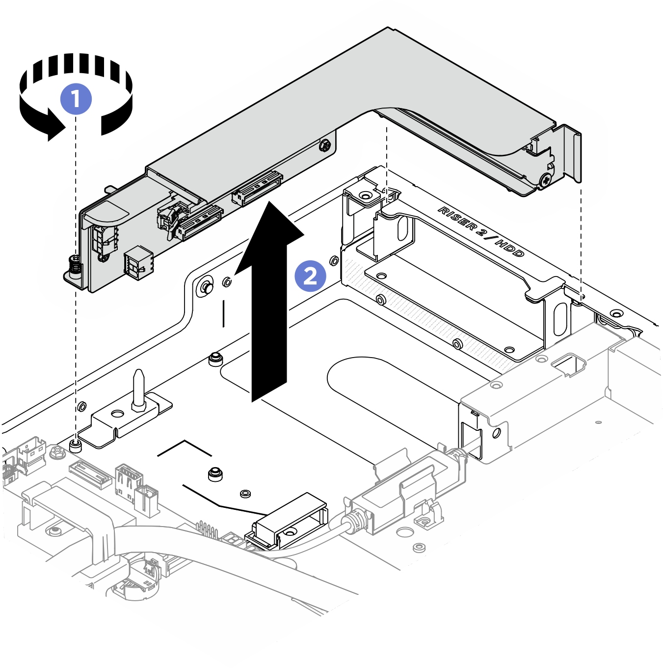
- Remove the PCIe riser assembly in riser 2 slot.
- Unfasten the thumbscrew on the PCIe riser.
- Lift the PCIe riser assembly out of the CPU complex.
- Disconnect the PCIe riser assembly cables. See PCIe riser cable routing for more information on the internal cable routing.Figure 5. PCIe riser assembly removal in riser 2 slot
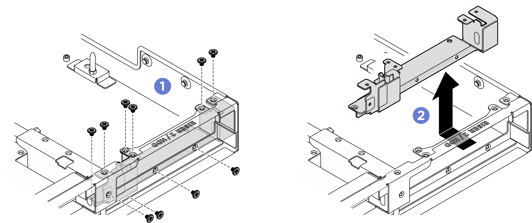
- If necessary, remove the rear riser support bracket in riser 2 slot.
- Unfasten the ten screw that secure the rear riser support bracket to the CPU complex.
- Lift the rear riser support bracket out of the riser slot.Figure 6. Removing rear riser support bracket
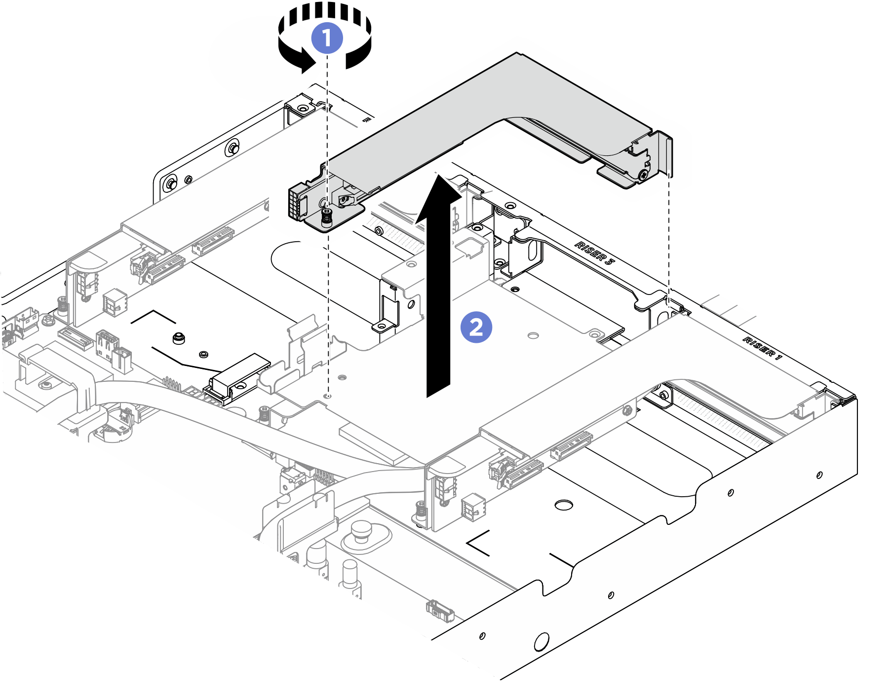
- Remove the PCIe riser assembly in riser 3 slot.
- Unfasten the thumbscrew on the PCIe riser assembly.
- Lift the PCIe riser assembly from the leakage sensor module bracket.
- Disconnect the PCIe riser assembly cables. See PCIe riser cable routing for more information on the internal cable routing.Figure 7. PCIe riser assembly removal in riser 3 slot
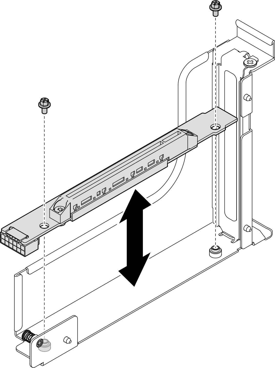
- If necessary, remove the cabled riser card from the riser cage. Unfasten the two screws to remove the PCIe riser card from the PCIe riser cage.Figure 8. Cabled riser card removal
After you finish
- If you are instructed to return the component or optional device, follow all packaging instructions, and use any packaging materials for shipping that are supplied to you.
- If you plan to recycle the component:
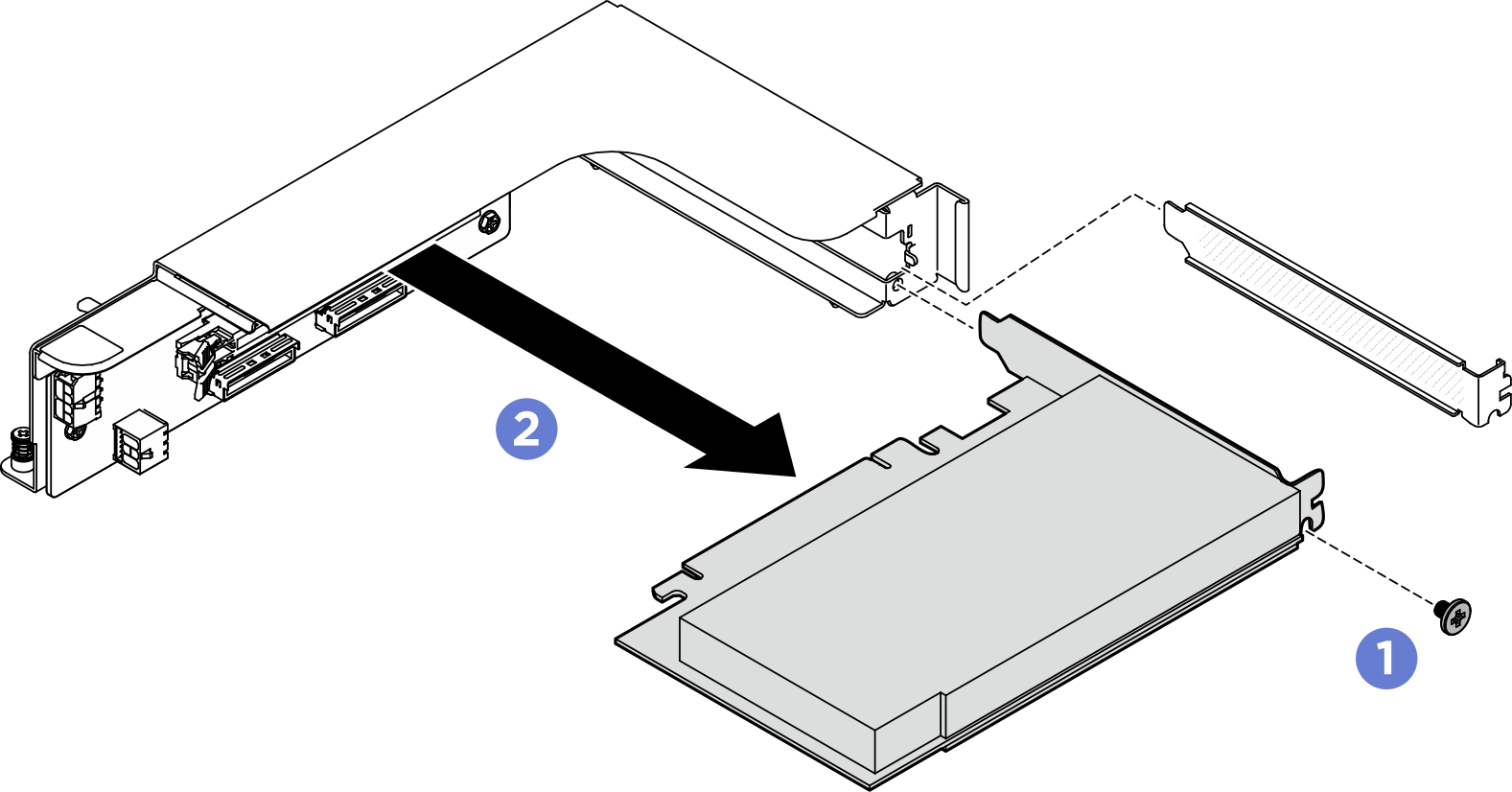
- Remove the rear PCIe adapter from the PCIe riser.
- Unfasten the screw that secures the rear PCIe adapter to the PCIe riser.
- Grasp the rear PCIe adapter by its edges and carefully pull it out of the PCIe slot.Figure 9. Rear PCIe adapter removal
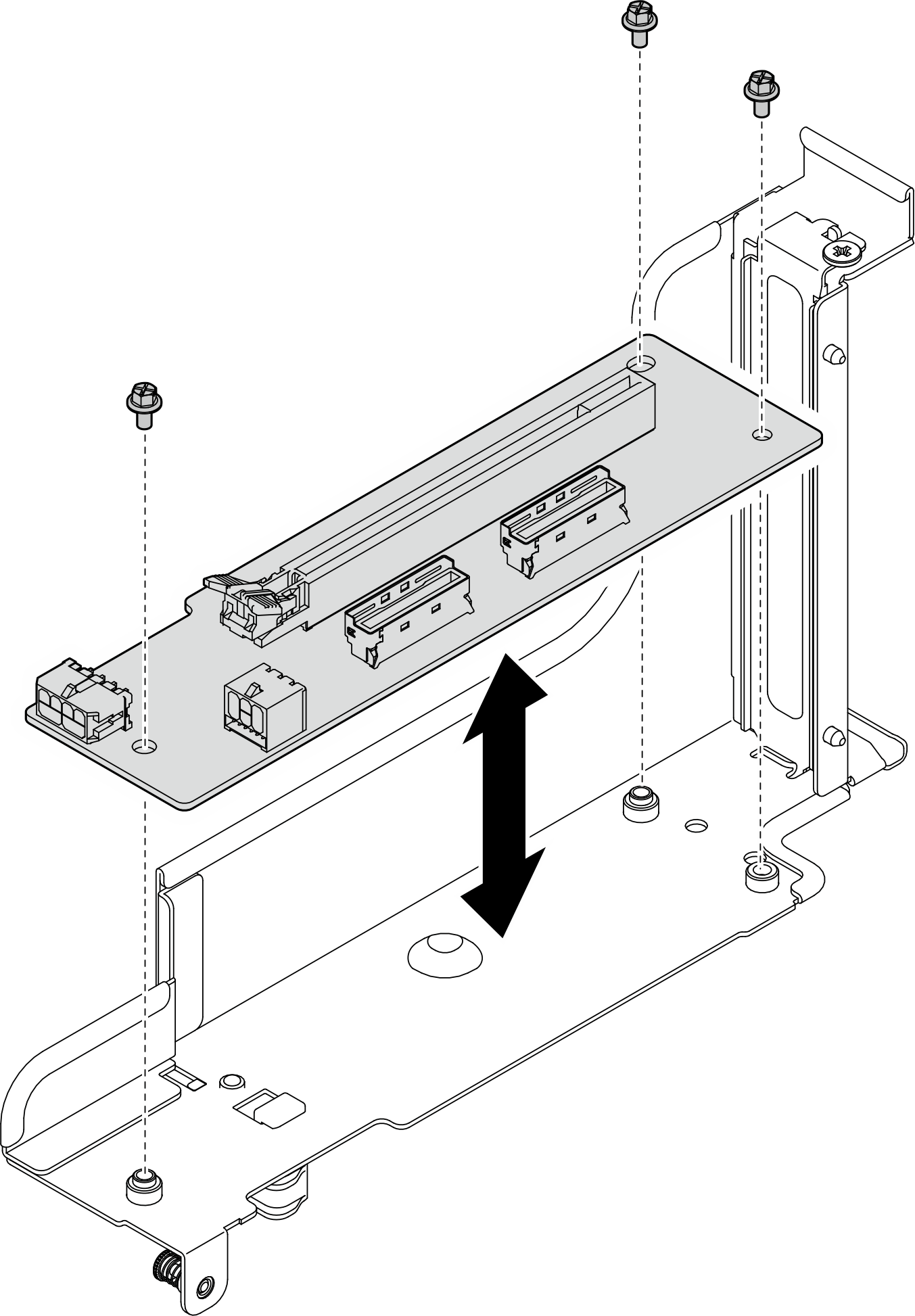
- Unfasten the three screws to remove the PCIe riser card from the PCIe riser cage.Figure 10. PCIe riser card removal
- Recycle the component in compliance with local regulations.
- Remove the rear PCIe adapter from the PCIe riser.
Give documentation feedback