Remove the system I/O board
Follow instructions in this section to remove the system I/O board. The procedure must be executed by a trained technician.
About this task
Attention
- Read Installation Guidelines and Safety inspection checklist to ensure that you work safely.
- Power off the server and peripheral devices and disconnect the power cords and all external cables. See Power off the server.
- If the server is installed in a rack, slide the server out on its rack slide rails to gain access to the top cover, or remove the chassis from the rack. See Remove the server from rack.
- Two people and one lifting device on site that can support up to 400 lb (181 kg) are required to perform this procedure. If you do not already have a lifting device available, Lenovo offers the Genie Lift GL-8 material lift that can be purchased at Data Center Solution Configurator. Make sure to include the Foot-release brake and the Load Platform when ordering the Genie Lift GL-8 material lift.
- m
- Prevent exposure to static electricity, which might lead to system halt and loss of data, by keeping static-sensitive components in their static-protective packages until installation, and handling these devices with an electrostatic-discharge wrist strap or other grounding system.
- After replacing the system I/O board, update the firmware to the specific version supported by the server. Make sure that you have the required firmware or a copy of the pre-existing firmware before you proceed.
Procedure
- Make preparations for this task.
- Remove the front top cover. See Remove the front top cover.
- Remove the rear top cover. See Remove the rear top cover.
- Remove the processor air baffle. See Remove the processor air baffle.
- If applicable, remove the rear drive cage. See Remove the rear drive cage.
- If applicable, remove the leakage sensor module bracket. See Remove the leakage sensor module bracket.
- Remove the system I/O board.
 Loosen the four screws securing both the system I/O board and the cable.
 Slide the system I/O board towards the system board until the notches are aligned to the retainer as illustrated. Lift the system I/O board out of the chassis.
 Disconnect the cable from the system I/O board.Figure 1. Removing the system I/O board
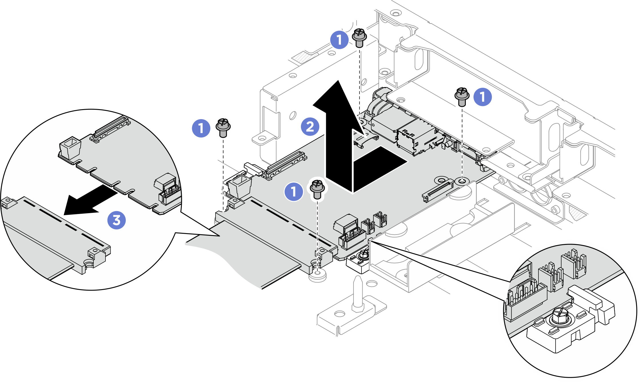
After you finish
- Install a replacement unit. See Install the system I/O board
- Complete the parts replacement. See Complete the parts replacement.
If you are instructed to return the component or optional device, follow all packaging instructions, and use any packaging materials for shipping that are supplied to you.
Give documentation feedback