Install the system I/O board
Follow instructions in this section to install the system I/O board. The procedure must be executed by a trained technician.
About this task
Important
This task must be operated by trained technicians that are certified by Lenovo Service. Do not attempt to remove or install the part without proper training and qualification.
Attention
- Read Installation Guidelines and Safety inspection checklist to ensure that you work safely.
- Touch the static-protective package that contains the component to any unpainted metal surface on the server; then, remove it from the package and place it on a static-protective surface.
- Prevent exposure to static electricity, which might lead to system halt and loss of data, by keeping static-sensitive components in their static-protective packages until installation, and handling these devices with an electrostatic-discharge wrist strap or other grounding system.
Firmware and driver download: You might need to update the firmware or driver after replacing a component.
Go to Drivers and Software download website for ThinkSystem SR780a V3 to see the latest firmware and driver updates for your server.
Go to Update the firmware for more information on firmware updating tools.
Procedure
Install the system I/O board.
 Connect the cable to the system I/O board.
 Align the notches on the system I/O board with the retainers as illustrated. Align the connectors on the system I/O board with the slots on the CPU complex; then, gently slide and insert the system I/O board into place.
 Tighten the four M3 screws (PH1, 4 x M3, 0.9 newton-meters, 8 inch-pounds) to secure the system I/O board and the cable.Figure 1. Installing the system I/O board
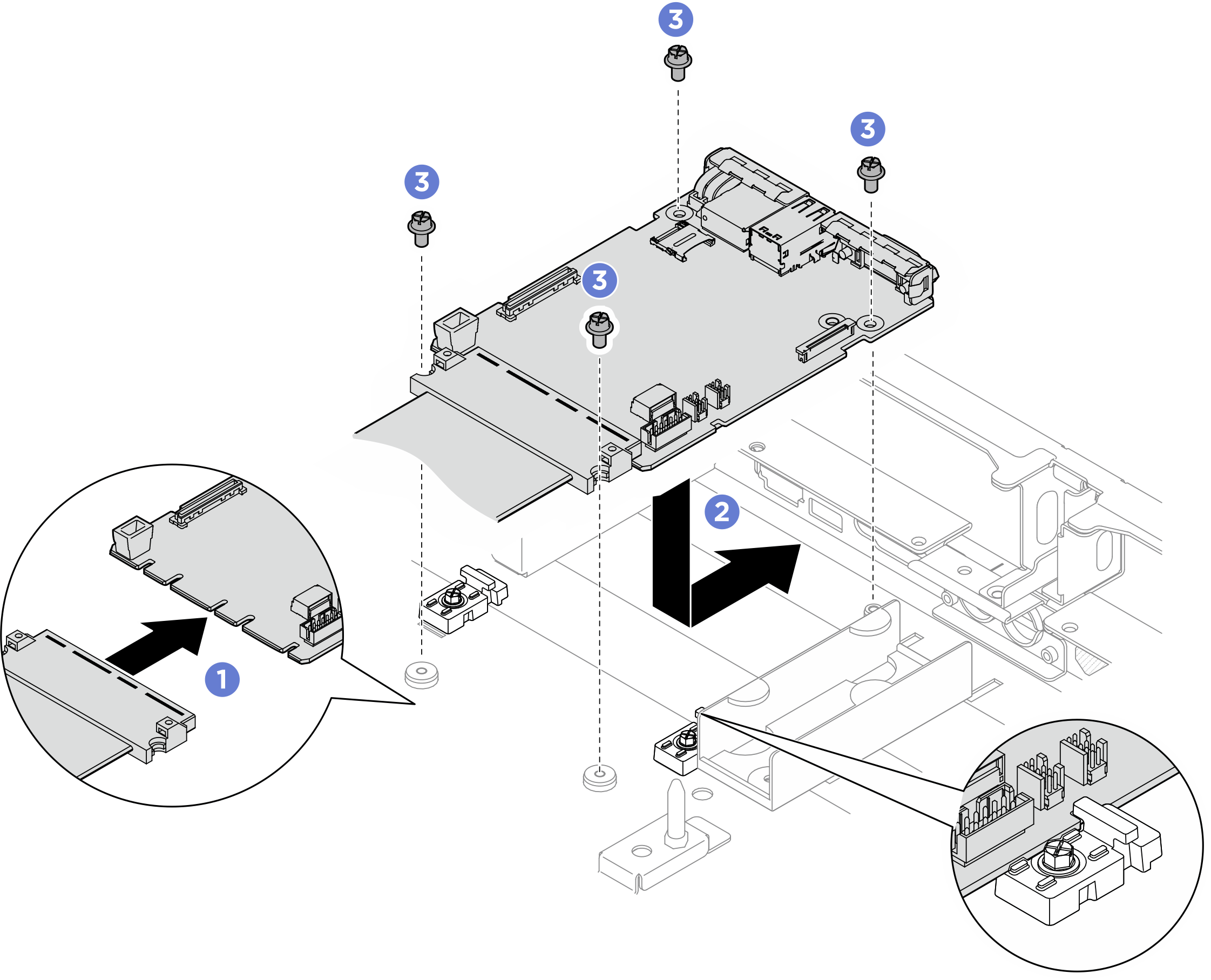
After you finish
- If applicable, reinstall the leakage sensor module bracket. See Install the leakage sensor module bracket.
- If applicable, reinstall the rear drive cage. See Install the rear drive cage.
- Reinstall the processor air baffle. See Install the processor air baffle.
- Reinstall the rear top cover. See Install the rear top cover.
- Reinstall the front top cover. See Install the front top cover.
- Reconnect the power cords and any cables that you removed.
- Power on the server and any peripheral devices. See Power on the server.
- Update the XCC/UEFI/LXPM/SCM FPGA firmware. See Update the firmware
- Restore the server configuration. See Restore the server configuration.
- Re-install the FoD key.
- Optionally, enable Secure Boot. See Enable UEFI Secure Boot.
Give documentation feedback