Front view of the server model with E3.S 1T bays
This section contains information on the front view of the server model with E3.S 1T bays.
Front view of the server model with E3.S 1T bays
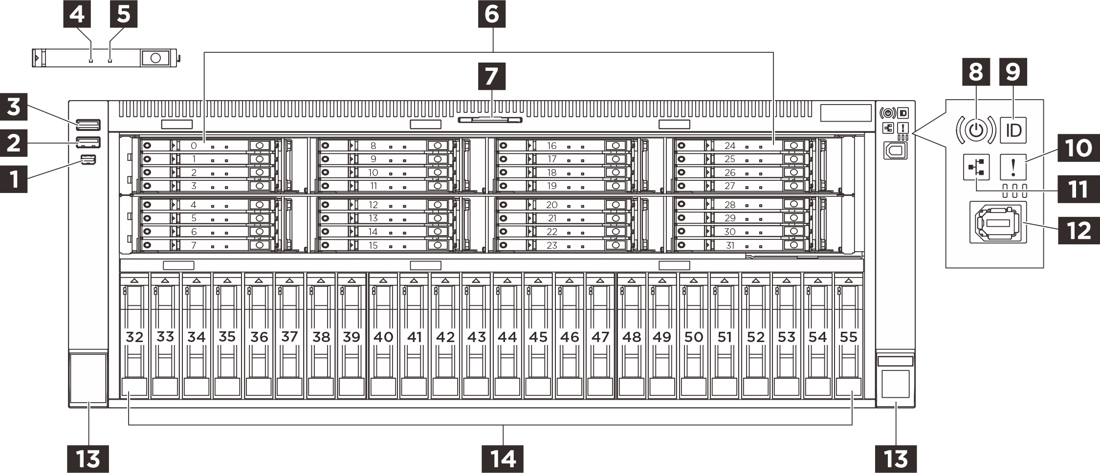
| 1 Mini DisplayPort connector | 2 USB 3.2 Gen 1 (5 Gbps) connector |
| 3 USB 3.2 Gen 1 (5 Gbps) with connector USB2.0 XCC management | 4 Drive status LED (yellow) |
| 5 Drive activity LED (green) | 6 E3.S bays |
| 7 Pull-out information tab | 8 Power button with LED (green) |
| 9 System ID button with LED (blue) | 10 System error LED (yellow) |
| 11 Network activity LED (green) | 12 External diagnostics connector |
| 13 Rack release latches | 14 2.5-inch drive bays |
1 Mini DisplayPort connector
The Mini DisplayPort (MiniDP) connector can be used to attach a high-performance monitor and a direct-drive monitor with a video converter, or the devices that use a MiniDP connector.
2 USB 3.2 Gen 1 (5 Gbps) connector
The USB 3.2 Gen 1 (5 Gbps) connector can be used to attach a USB-compatible device, such as a USB keyboard, USB mouse, or USB storage device.
3 USB 3.2 Gen 1 (5 Gbps) with connector USB 2.0 XCC management
The connector can function as a regular USB 3.2 Gen 1 connector to the host OS; it can be used to attach a USB-compatible device, such as a USB keyboard, USB mouse, or USB storage device.
In addition, the connector can function as a USB 2.0 Lenovo XClarity Controller management port.
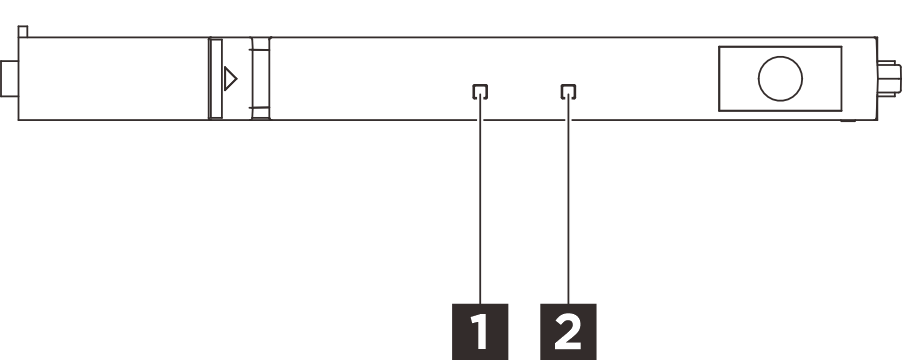
4 5 E3.S drive LEDs
Each E3.S drive comes with an activity LED and a status LED.
| LED | Status | Description |
|---|---|---|
| 1 Drive status LED (yellow) | Solid on | The drive has an error. |
| Slow blinking (about one flash per second) | The drive is being rebuilt. | |
| Fast blinking (about three flashes per second) | The drive is being identified. | |
| 2 Drive activity LED (green) | Solid on | The drive is powered but not active. |
| Blinking | The drive is being accessed (reading or writing data). |
6 E3.S drive bays
The drive bays are used to install E3.S hot-swap drives. When you install drives, follow the order of the drive bay numbers. The EMI integrity and cooling of the server are protected by having all drive bays occupied. The vacant drive bays must be occupied by drive bay fillers or drive fillers.
7 Pull-out information tab
This tab contains network information such as MAC address and XCC network access label.
8 Power button with LED (green)
| Status | Color | Description |
|---|---|---|
| Solid on | Green | The server is on and running. |
| Slow blinking (about one flash per second) | Green | The server is off and is ready to be powered on (standby state). |
| Fast blinking (about four flashes per second) | Green |
|
| Off | None | Power is not present, or the power supply has failed. |
9 System ID button with LED (blue)
Use this system ID button and the blue system ID LED to visually locate the server. A system ID LED is also located on the rear of the server. Each time you press the system ID button, the state of both the system ID LEDs changes. The LEDs can be changed to on, blinking, or off. You can also use the Lenovo XClarity Controller or a remote management program to change the state of the system ID LEDs to assist in visually locating the server among other servers.
10 System error LED (yellow)
| Status | Color | Description | Action |
|---|---|---|---|
| On | Amber | An error has been detected on the server. Causes might include but are not limited to the following errors:
|
Note For server models with |
| Off | None | The server is off or the server is on and is working correctly. | None. |
11 Network activity LED (green)
| Status | Color | Description |
|---|---|---|
| On | Green | The server is connected to a network. |
| Blinking | Green | The network is connected and active. |
| Off | None | The server is disconnected from the network. Note If the network activity LED is off when an OCP module is installed, check the network ports in the rear of your server to determine which port is disconnected. |
12 External diagnostics connector
The connector is for connecting an external diagnostics handset. See External diagnostics handset for more details.
13 Rack release latches
If your server is installed in a rack, you can use the rack latches to help you slide the server out of the rack. You also can use the rack latches and screws to secure the server in the rack so that the server cannot slide out, especially in vibration-prone areas.
14 2.5-inch drive bays
The drive bays are used to install hot-swap 2.5-inch drives. When you install drives, follow the order of the drive bay numbers. The EMI integrity and cooling of the server are protected by having all drive bays occupied. The vacant drive bays must be occupied by drive bay fillers or drive fillers.