Rear view
The rear of the server provides access to several components, including the power supplies, PCIe adapters, serial port, and Ethernet ports.
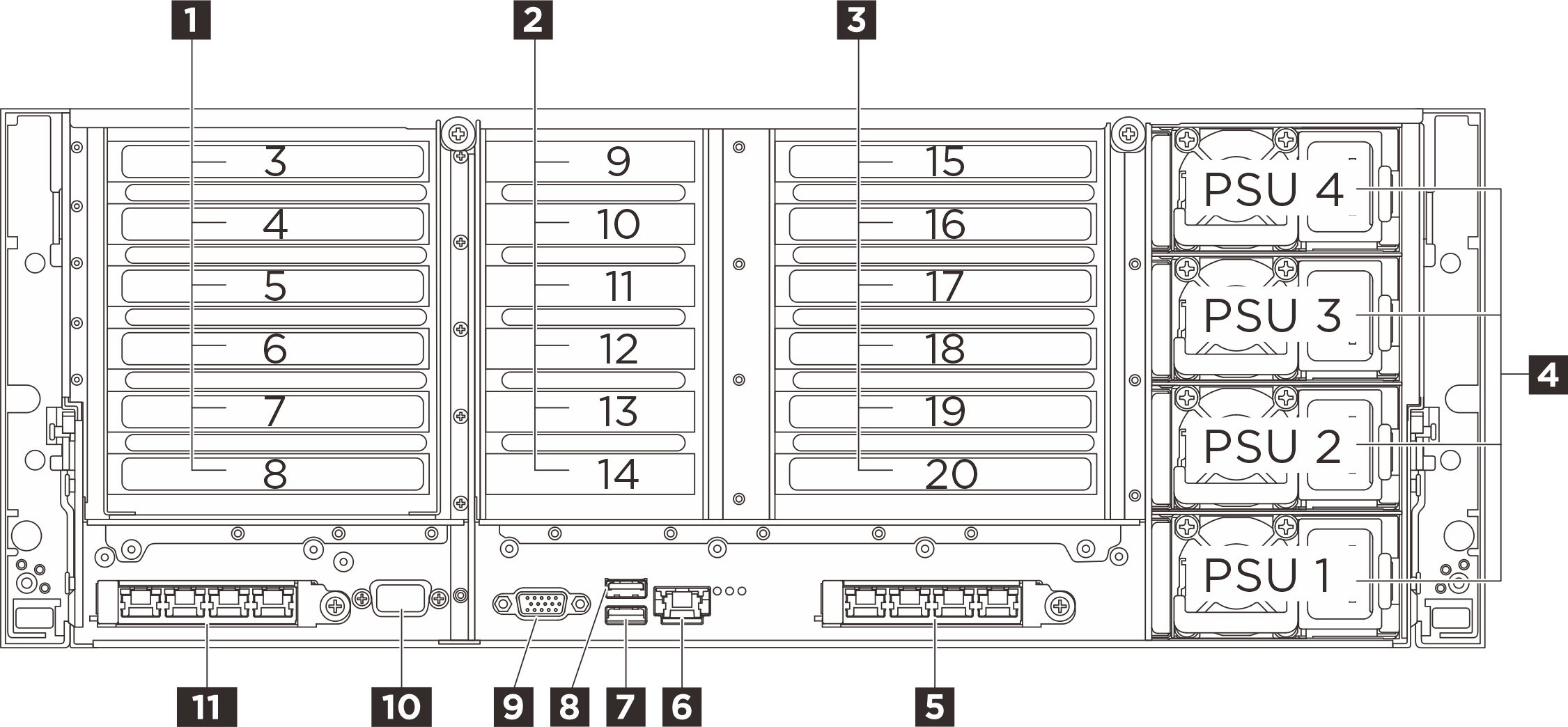
| 1 PCIe riser 1 (PCIe slot 3-8) | 2 PCIe riser 2 (PCIe slot 9-14) |
| 3 PCIe riser 3 (PCIe slot 15-20)* | 4 Power supply bays 1-4 |
| 5 OCP slot 2 | 6 XCC system management port (1 GB RJ-45) |
| 7 USB 3.2 Gen 1 (5Gbps) connector with USB 2.0 XCC system management (depending on the configuration) | 8 USB 3.2 Gen 1 (5 Gbps) connector |
| 9 VGA connector | 10 Serial port (optional) |
| 11 OCP slot 1 |
1 PCIe riser 1
See the following table for PCIe slots corresponding to the PCIe risers.
| PCIe slot | x8x8 PCIe G4 riser | x8x16x8x16x16x16 PCIe G5 riser |
|---|---|---|
| Slot 3 | Not supported | x16 (Gen5 x8) |
| Slot 4 | Not supported | x16 (Gen5 x16)* |
| Slot 5 | Not supported | x16 (Gen4 x8) |
| Slot 6 | Not supported | x16 (Gen5 x16)* |
| Slot 7 | x16 (Gen4 x8) | x16 (Gen5 x16) |
| Slot 8 | x16 (Gen4 x8) | x16 (Gen5 x16) |
* Slot 4 supports a double-wide GPU that occupies slot 3 and 4.
* Slot 6 supports a double-wide GPU that occupies slot 5 and 6.
2 PCIe riser 2
See the following table for PCIe slots corresponding to the PCIe riser.
| PCIe slot | x8x8x8x8x8x8 PCIe G5 riser |
|---|---|
| Slot 9 | x16 (Gen5 x8) |
| Slot 10 | x16 (Gen5 x8) |
| Slot 11 | x16 (Gen5 x8) |
| Slot 12 | x16 (Gen5 x8) |
| Slot 13 | x16 (Gen5 x8) |
| Slot 14 | x16 (Gen5 x8) |
3 PCIe riser 3
See the following table for PCIe slots corresponding to the PCIe risers.
| PCIe slot | x8x8 PCIe G4 riser | x8x8 PCIe G4 riser (with M.2 cage) | x8x16x8x16x16x16 PCIe G5 riser | x8x16x8x16x16x16 PCIe G5 riser (with M.2 cage) |
|---|---|---|---|---|
| Slot 15 | Not supported | M.2 drive bays (optional) | x16 (Gen5 x8) | x16 (Gen5 x8) |
| Slot 16 | Not supported | Not supported | x16 (Gen5 x16)* | x16 (Gen5 x16)* |
| Slot 17 | Not supported | Not supported | x16 (Gen4 x8) | x16 (Gen4 x8) |
| Slot 18 | Not supported | Not supported | x16 (Gen5 x16)* | x16 (Gen5 x16)* |
| Slot 19 | x16 (Gen4 x8) | x16 (Gen4 x8) | x16 (Gen5 x16) | x16 (Gen5 x16) |
| Slot 20 | x16 (Gen4 x8) | x16 (Gen4 x8) | x16 (Gen5 x16) | M.2 drive bays (optional) |
* Slot 16 supports a double-wide GPU that occupies slot 15 and 16.
* Slot 18 supports a double-wide GPU that occupies slot 17 and 18.
4 Power supply bays 1-4 (bottom to top)
Install power supply units to these bays, connect them to power cords. Make sure the power cords are connected properly. See Technical specifications for the power supplies supported by this system.
For information about the LEDs, see Power supply LEDs.
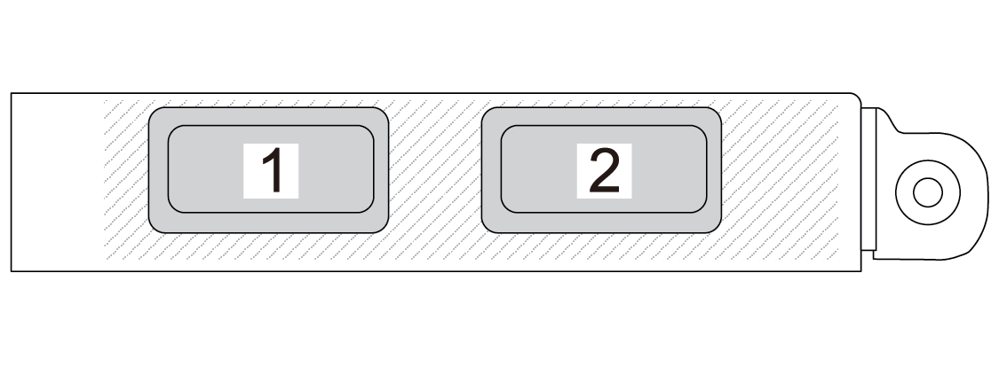
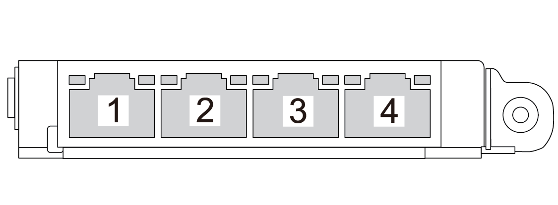
5 11 OCP slots
6 XCC system management port (1 GB RJ-45)
The server has a 1 GB RJ-45 connector dedicated to Lenovo XClarity Controller (XCC) functions. Through the system management port, you can access the Lenovo XClarity Controller directly by connecting your laptop to the management port using an Ethernet cable. Make sure that you modify the IP settings on the laptop so that it is on the same network as the server default settings. A dedicated management network provides additional security by physically separating the management network traffic from the production network.
7 USB 3.2 Gen 1 (5Gbps) connector with USB 2.0 XCC system management (depending on the configuration)
The connector can function as a regular USB 3.2 Gen 1 connector to the host OS; it can be used to attach a USB-compatible device, such as a USB keyboard, USB mouse, or USB storage device.
When there are no USB connectors at the front, this connector can function as a USB 2.0 Lenovo XClarity Controller management port.
8 USB 3.2 Gen 1 (5 Gbps) connectors
The connector can be used to attach a USB-compatible device, such as a USB keyboard, USB mouse, or USB storage device.
9 VGA connector
Connect a monitor to this connector.
10 Serial port (optional)
Connect a 9-pin serial device to this connector. The serial port is shared with XCC. XCC can take control of the shared serial port to redirect serial traffic, using Serial over LAN (SOL).