Guideline for cable routing for 2.5-inch drives
General guideline for cable routing for 2.5-inch drives.
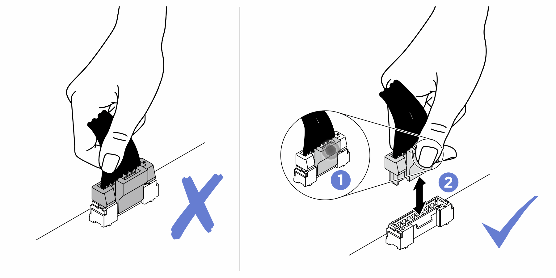
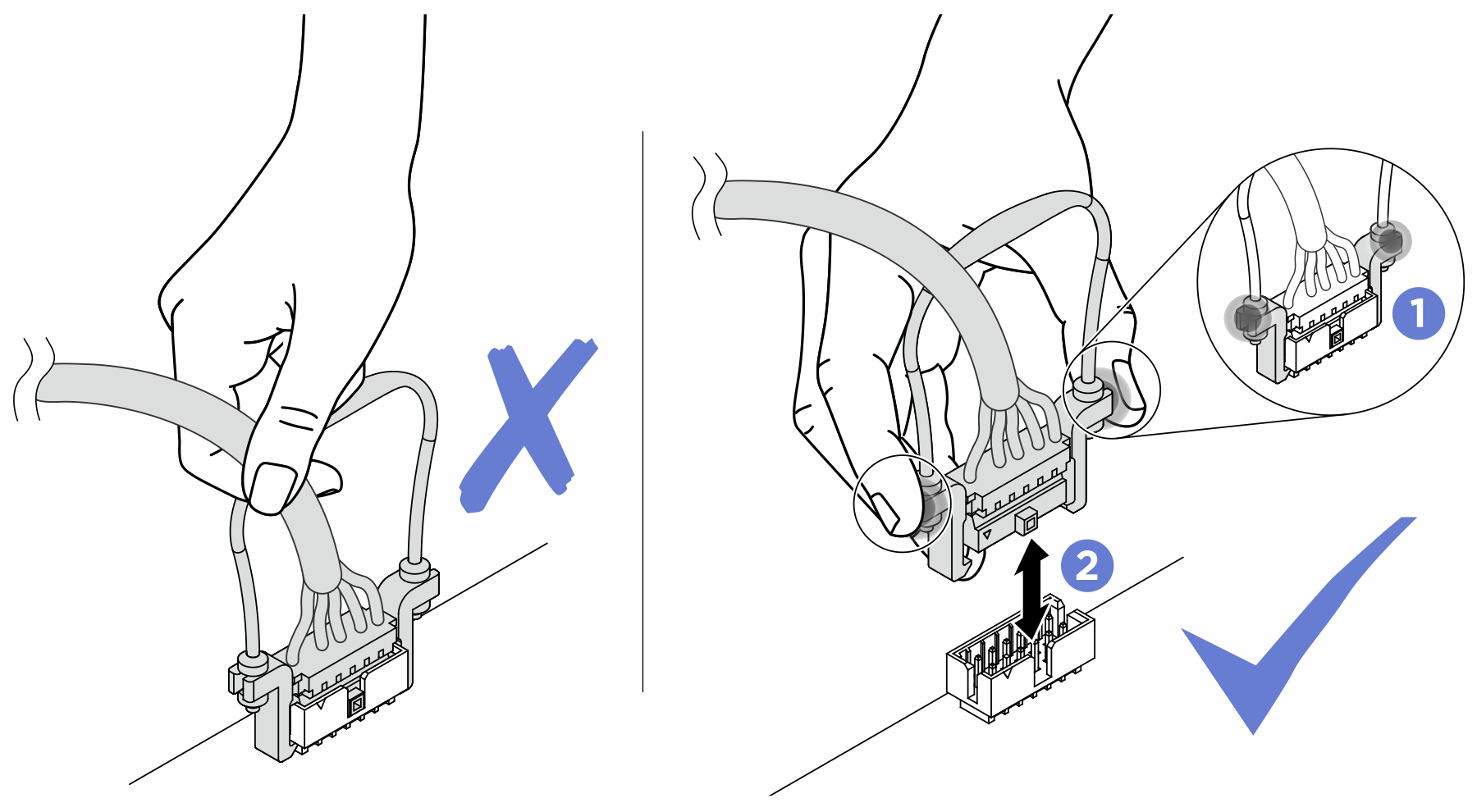
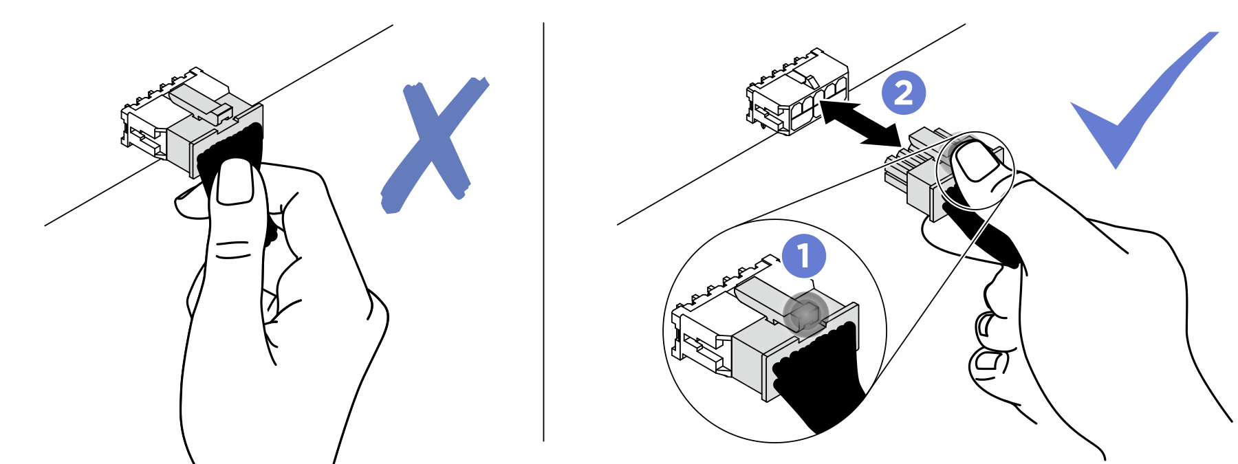
Connect cable connectors vertically or horizontally in alignment with the orientations of the corresponding cable sockets, avoiding any tilt.
- To disconnect cables from the system board, do as follows:
Press and hold all latches, release tabs, or locks on cable connectors to release the cable connectors.
- Remove the cable connectors vertically or horizontally in alignment with the orientations of the corresponding cable sockets, avoiding any tilt.NoteThe cable connectors might look different from those in the illustration, but the removal procedure is the same.
Make sure all the signal cables go through the cable guides.
Figure 1. Cable guide locations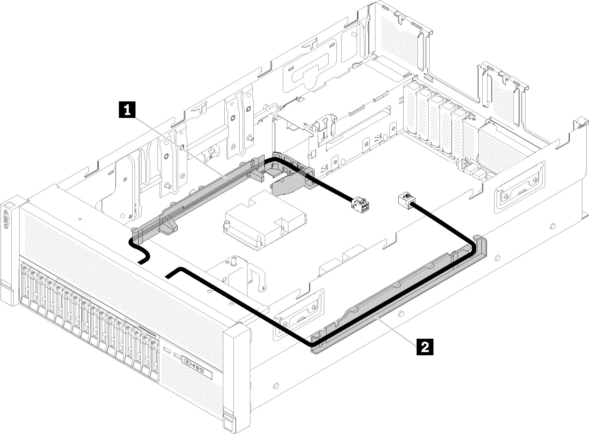
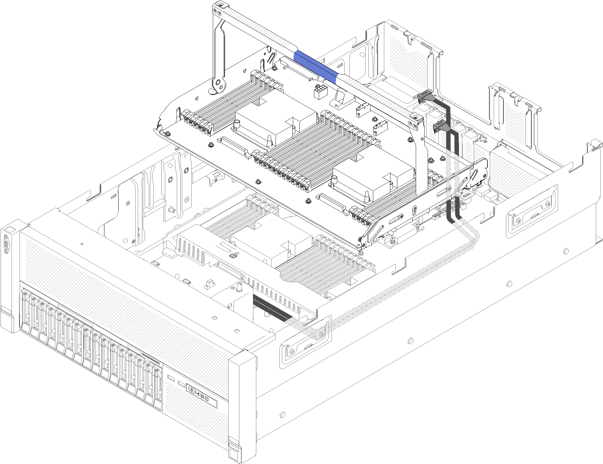
Table 1. Cable guide 1 Cable guide 2 Cable guide - If the processor and memory expansion tray is installed in the server, lift the tray and route the direct NVMe signal cables in the cable guide and behind the tray.Figure 2. Routing the NVMe cables to the processor and memory expansion tray
Connect the direct NVMe signal cables to the NVMe connectors on the processor and memory expansion tray.
Figure 3. Connecting the NVMe cables to the processor and memory expansion tray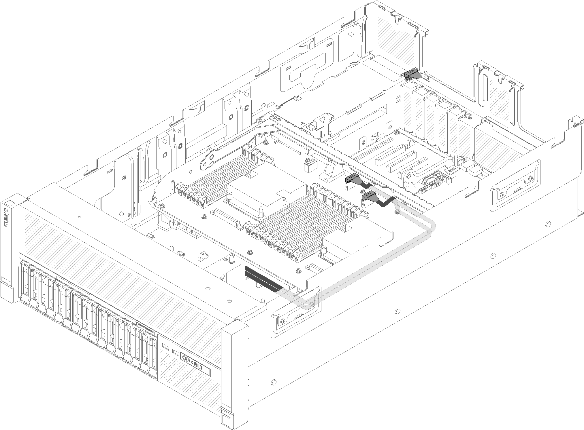
Remove the fan cage assembly (see Remove the fan cage assembly).
Remove the system board air baffle (see Remove the system board air baffle and the power interposer) or the processor and memory expansion tray and the processor and memory expansion tray air baffle (see Remove the processor and memory expansion tray).
Connecting power cable
Connect power cables for drive backplanes as in the following illustration.
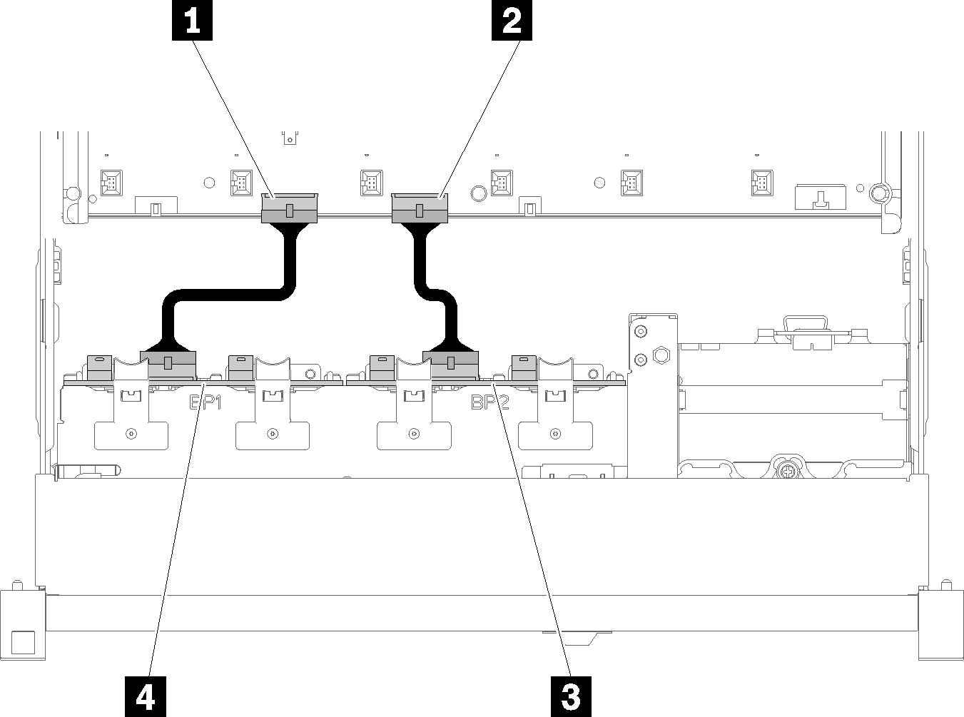
| 1 Power cable connector on the system board | 3 Power cable connector on the drive backplane |
| 2 Power cable connector on the system board | 4 Power cable connector on the drive backplane |
- 2.5-inch SATA/SAS 8-bay backplane (referred to as “8-bay backplane”)
- 2.5-inch AnyBay 8-bay backplane (referred to as “AnyBay backplane”)
4U PCIe riser assemblies can be installed when the PCIe slot 3 or 13 are not occupied by PCIe adapters, make sure the slots for 4U PCIe riser cards are available before the riser card installation.