Install the power supply unit
Follow this procedure to install the power supply unit.

To avoid a shock hazard:
- Connect all power cords to a properly wired and grounded electrical outlet/source.
- Connect any equipment that will be attached to this product to properly wired outlets/sources.
- When possible, use one hand only to connect or disconnect signal cables.
- Never turn on any equipment when there is evidence of fire, water, or structural damage.
- The device might have more than one power cord, to remove all electrical current from the device, ensure that all power cords are disconnected from the power source.
Never remove the cover on a power supply or any part that has this label attached. Hazardous voltage, current, and energy levels are present inside any component that has this label attached. There are no serviceable parts inside these components. If you suspect a problem with one of these parts, contact a service technician.
Read Safety inspection checklist and Installation guidelines to ensure that you work safely.
Touch the static-protective package that contains the component to any unpainted metal surface on the server; then, remove it from the package and place it on a static-protective surface.
Make sure the type of power supply is applicable to server drive configuration. See Specifications for more information.
- A video of this procedure is available at YouTube.
Procedure
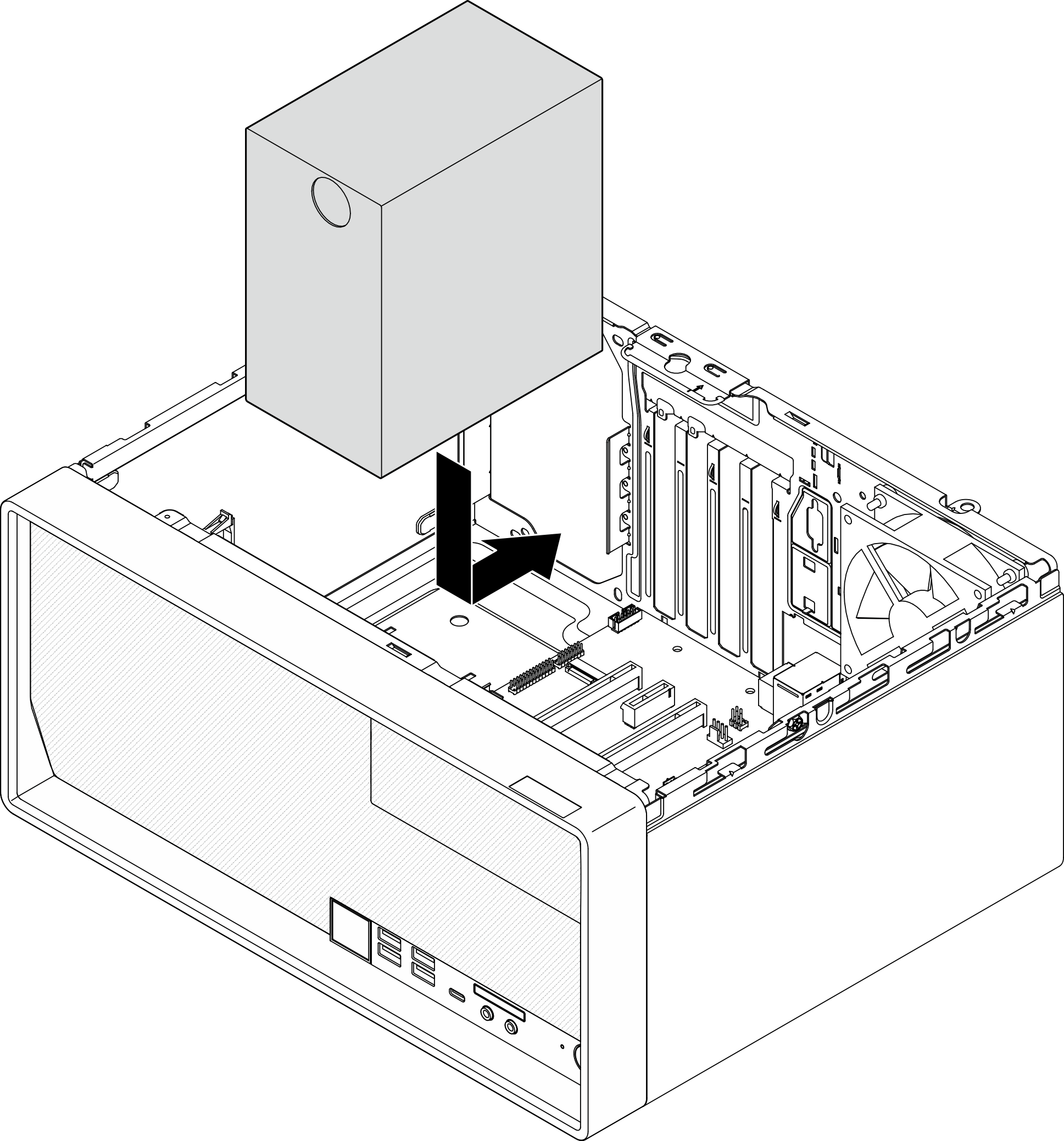
- Lower the power supply into the chassis, and slide it toward the opening on the rear side of chassis until the release tab snaps into place.Figure 1. Installing the power supply to the chassis
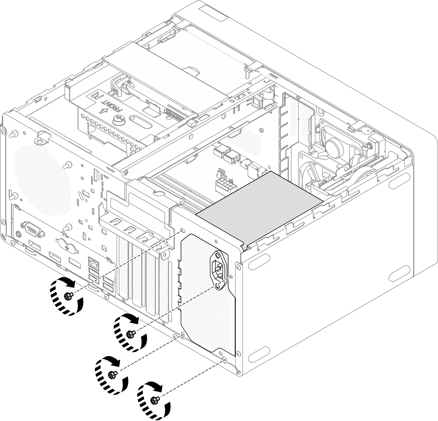
- From outside of the chassis, fasten the four screws to secure the power supply unit to the chassis.Figure 2. Securing the power supply units to the chassis
Reinstall bay 1 drive cage and the 3.5-inch drive, see Simple-swap drive and drive cage (bay 1-2) replacement.
If applicable, reinstall bay 2 drive cage and the 2.5-inch drive, see Simple-swap drive and drive cage (bay 1-2) replacement.
Proceed to complete the parts replacement, see Complete the parts replacement.