Cable routing for drive bay 1 and bay 2
Read this section to learn about cable routing for the drive in bay 1 and bay 2.
Drive bay 1
Figure 1. Cable routing for drive bay 1
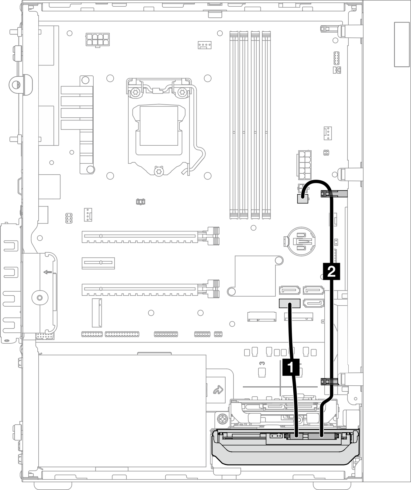
| Cable | From | To |
|---|---|---|
| 1 1st 3.5 or 2.5 HDD SATA cable, 185 mm | Bay 1 drive signal connector | SATA 1 connector |
| 2 1st 3.5 and 2.5 HDD Power Cable (300 mm + 80 mm) | Bay 1 drive power connector | SATA power 2 connector |
Make sure to follow the Cable routing guidelines
in Internal cable routing.
For the system-board connector locations, see System board components.
Drive bay 2
Figure 2. Cable routing for drive bay 2
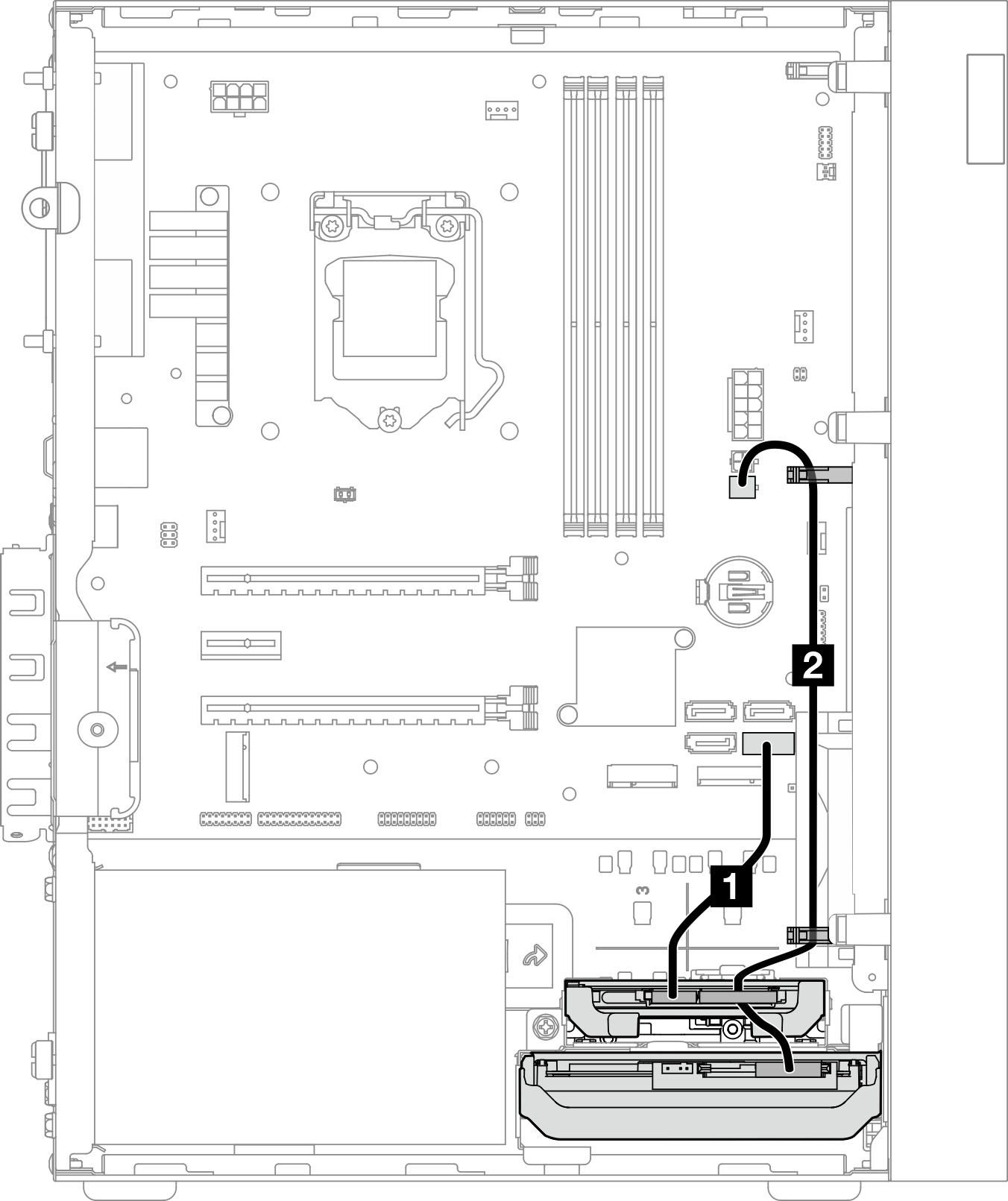
| Cable | From | To |
|---|---|---|
| 1 1st 3.5 or 2.5 HDD SATA cable, 185 mm | Bay 2 drive signal connector | SATA 2 connector |
| 2 1st 3.5 and 2.5 HDD Power Cable (300 mm + 80 mm) | Bay 2 drive power connector and bay 1 drive power connector | SATA power 2 connector |
Make sure to follow the Cable routing guidelines
in Internal cable routing.
For the system-board connector locations, see System board components.
Give documentation feedback