Cable routing for the RAID adapter and drives
Follow the instructions in this section to learn how to do cable routing for the RAID adapter and drives.
RAID adapter cable
 The break lines indicate that part of the cable is hidden in the illustration.
Figure 1. Cable for 5350-8i or 4350-8i
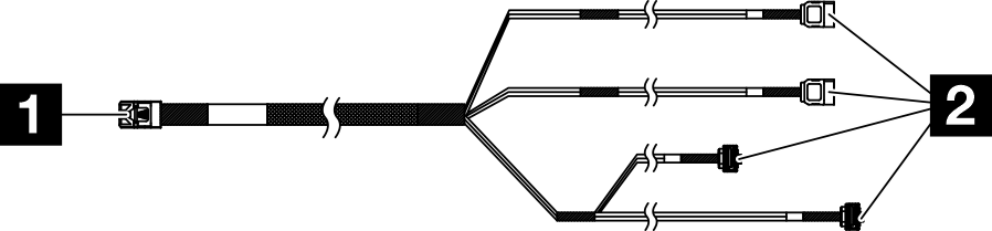
Figure 2. Cable for 545-8i
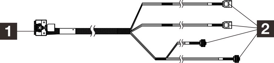
| 1 Connector for the RAID adapter (connector C0) | 2 Connectors for the drives |
Power cable routing
Figure 3. Power cable routing
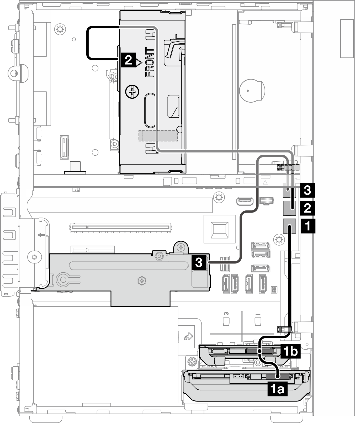
| From (drive bay 0/1/2/3) | To (system board) | Cable |
|---|---|---|
1a Bay 0 drive power connector 1b Bay 1 drive power connector | 1 SATA power 1 connector | 4pin power cable, 300 mm/80 mm |
| 2 Bay 2 drive power connector | 2 SATA power 2 connector | 4pin power to HDD&Slim ODD, 300 mm/330 mm/120 mm |
| 3 Bay 3 drive power connector | 3 SATA power 3 connector | 4pin power cable, 380 mm |
Signal cable routing
Figure 4. Signal cable routing
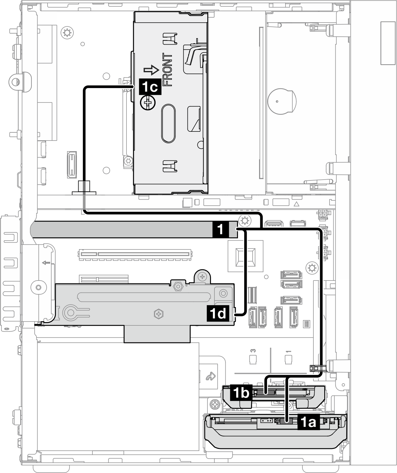
| From | To | Cable | |
|---|---|---|---|
| 1 C0 connector on the RAID adapter | 1a Bay 0 drive signal connector | cable labeled as 0 |
|
| 1b Bay 1 drive signal connector | cable labeled as 1 | ||
| 1c Bay 2 drive signal connector | cable labeled as 2 | ||
| 1d Bay 3 drive signal connector | cable labeled as 3 | ||
Note When no bay 1/2/3 drive is installed, the cable labeled as 1/2/3 is left unused. | |||
For the system-board connector locations, see System-board connectors for cable routing.
Give documentation feedback