Cable routing for drive bay 0 and bay 1
Follow the instructions in this section to learn how to do cable routing for the drives in bay 0 and bay 1.
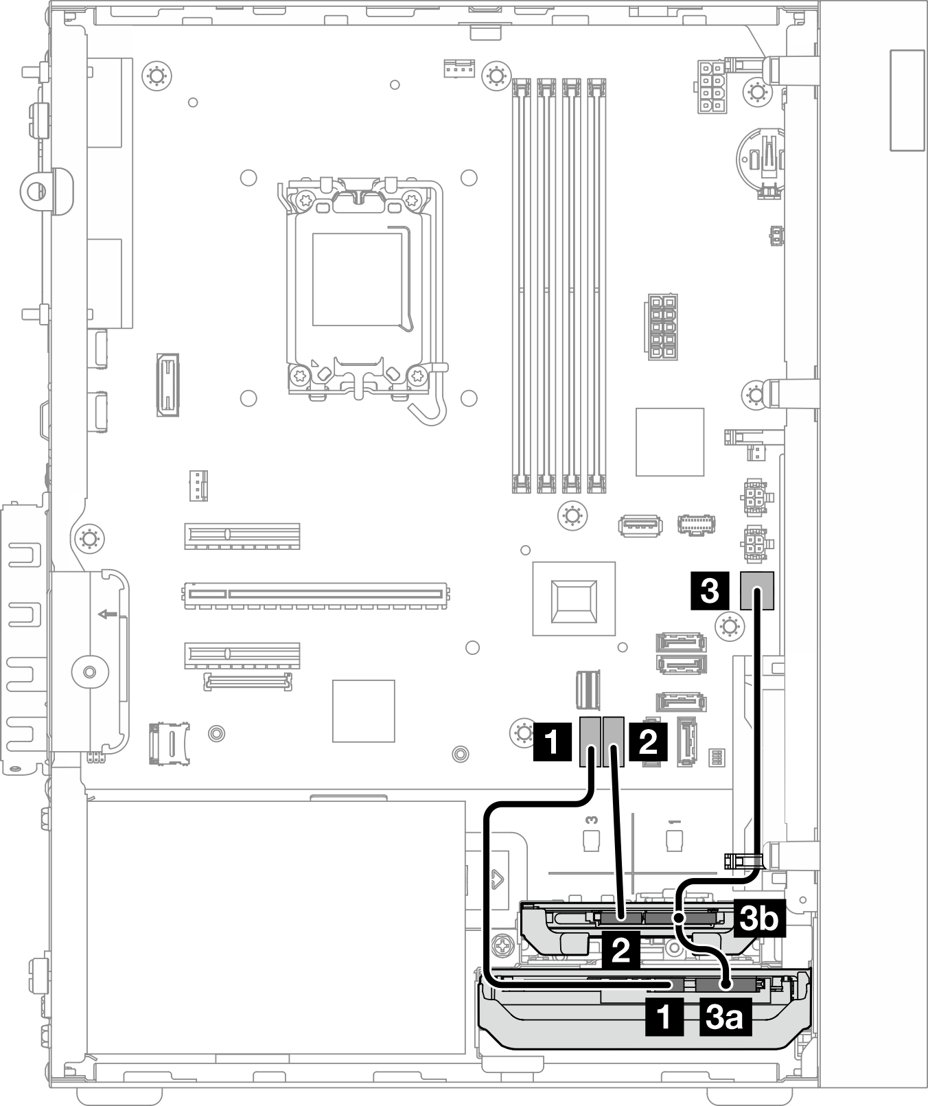
Figure 1. Cable routing for drive bay 0 and bay 1
| From | To (system board) | Cable |
|---|---|---|
| 1 Bay 0 drive signal connector | 1 SATA 0 connector | 7pin SATA to 7pin RA SATA cable, 185 mm |
| 2 Bay 1 drive signal connector | 2 SATA 1 connector | 7pin SATA to 7pin RA SATA cable, 185 mm |
3a Bay 0 drive power connector 3b Bay 1 drive power connector | 3 SATA power 1 connector | 4pin power cable, 300 mm/80 mm |
Note When no bay 1 drive is installed, cable connector 3b is left unused. | ||
For the system-board connector locations, see System-board connectors for cable routing.
Give documentation feedback