Install DIMM
Use this information to install a DIMM.


Memory modules are sensitive to static discharge and require special handling. In addition to the standard guidelines for Handling static-sensitive devices:
Always wear an electrostatic-discharge strap when removing or installing memory modules. Electrostatic-discharge gloves can also be used.
Never hold two or more memory modules together so that they touch. Do not stack memory modules directly on top of each other during storage.
Never touch the gold memory module connector contacts or allow these contacts to touch the outside of the memory-module connector housing.
Handle memory modules with care: never bend, twist, or drop a memory module.
Procedure performed by: customer or field service
The following illustration shows the location of the DIMM connectors on the system board. The following illustration shows the location of the DIMM connectors on the system board.
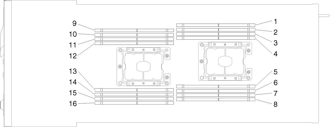
Complete the following steps to install a DIMM:
Before installing a memory module, make sure that you understand the required installation order, depending on whether you are implementing memory mirroring, memory rank sparing, or independent memory mode. See Installation order for the required installation order.
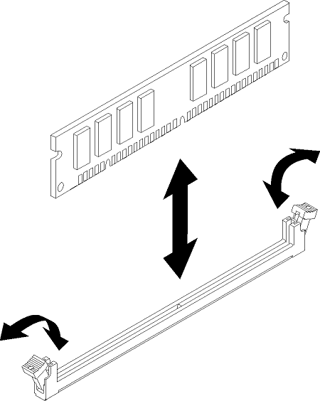
- Firmly press the DIMM straight down into the connector by applying pressure on both ends of the DIMM simultaneously. The retaining clips snap into the locked position when the DIMM is firmly seated in the connector.Figure 2. DIMM installation
 Note
NoteIf there is a gap between the DIMM and the retaining clips, the DIMM has not been correctly inserted; open the retaining clips, remove the DIMM, and then reinsert it.
The installation of the DIMM is now complete.
After you install a DIMM, complete the following steps:
Reinstall the air baffle (see http://thinksystem.lenovofiles.com/help/topic/7X21/install_the_air_baffle.html).
Reinstall the compute node cover (see http://thinksystem.lenovofiles.com/help/topic/7X21/install_the_compute_node_cover.html).
Reinstall the compute node (see http://thinksystem.lenovofiles.com/help/topic/7X21/install_a_compute_node_in_the_chassis.html).
Check the power LED to make sure it transitions between fast blink and slow blink to indicate the node is ready to be powered on.
Power on the node.
Exit maintenance mode.
Verify that the DIMM memory failure is resolved by reloading the system. If successful, no POST errors appear during the booting process.
If you are instructed to return the component or optional device, follow all packaging instructions, and use any packaging materials for shipping that are supplied to you.