Installing the microprocessor 2 expansion board
Use this information to install the microprocessor 2 expansion board
Read the safety information in Safety and Installation guidelines.
If you are replacing a server component in the server, you need to turn off the server and peripheral devices, and disconnect the power cords and all external cables.
To install the microprocessor 2 expansion board, complete the following steps.
- Install the microprocessor 2 expansion board side bracket.
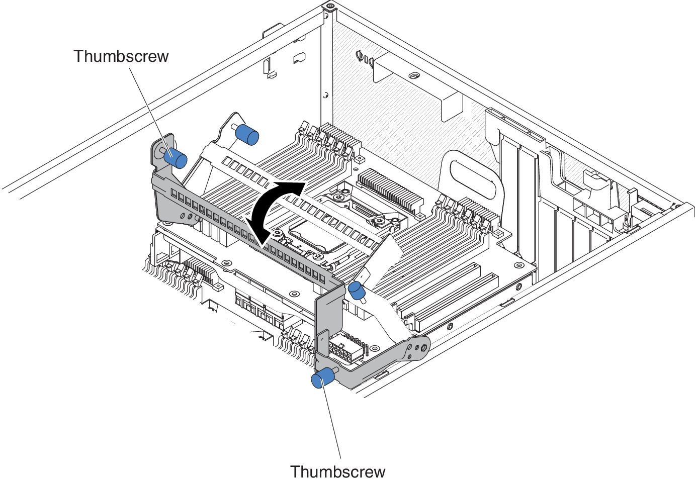
- Align the side bracket with the holes on the chassis and install the side bracket on the system board.Figure 1. Align the side bracket
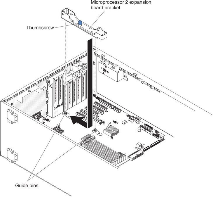
- Align the side bracket with the holes on the chassis and install the side bracket on the system board.
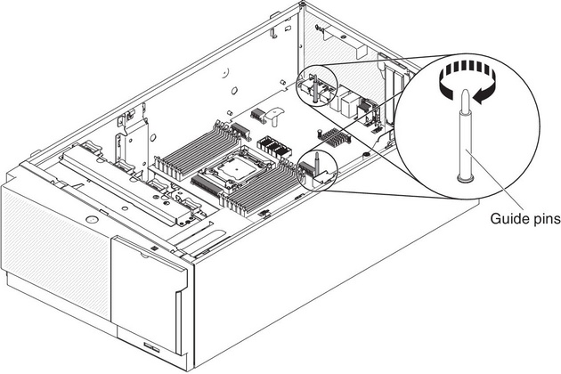
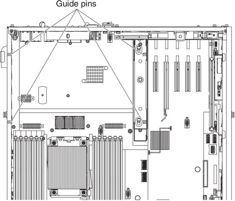
- Install the two guide pins on the system board.Figure 2. Install two guide pins
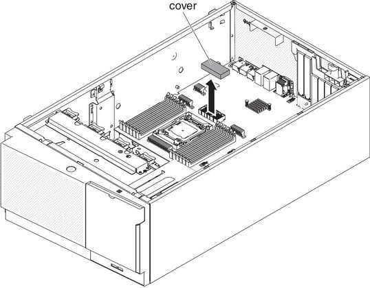
- Remove the cover on the microprocessor 2 expansion board connector from the system board. Figure 3. Remove cover
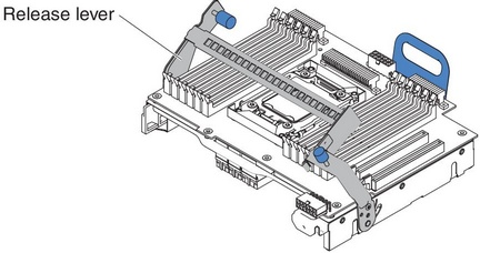
- Make sure the microprocessor 2 expansion board release lever is in the open position.Figure 4. Release lever in open position
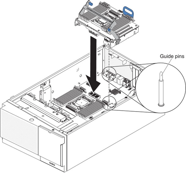
- Align the microprocessor 2 expansion board to the guide pins on the bottom of the chassis and the side bracket. Figure 5. Align CPU 2 expansion board
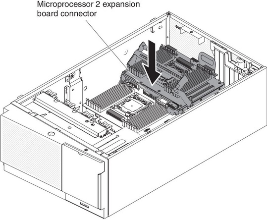
- Align the holes on the microprocessor 2 expansion board to the guide pins on the system board. Install the microprocessor 2 expansion board on the system board.Figure 6. Align holes in CPU 2
- Press the microprocessor 2 expansion board firmly and horizontally to the system board.Figure 7. Press CPU 2 expansion board on system board
 Note
Note- Static electricity that is released to internal server components when the server is powered-on might cause the server to halt, which might result in the loss of data. To avoid this potential problem, always use an electrostatic-discharge wrist strap or other grounding system when you work inside the server with the power on.
- Make sure that none of the server cables are caught under the microprocessor 2 expansion board.
- Rotate the release lever toward the front of the server to secure the microprocessor 2 expansion board in place.Figure 8. Rotate release lever to the front
 NotePress the microprocessor 2 expansion board connector to make sure the connector is seated securely on the system board.
 - Route the power cable to the microprocessor 2 expansion board power connector from the power paddle card.Figure 9. Route the power cable
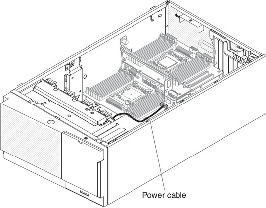
- Reconnect any cable to the microprocessor 2 expansion board that you disconnected during removal (see System-board internal connectors and Internal cable routing and connectors).Figure 10. Connect the power cable
 Note
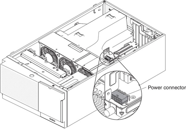
Note- Connect the power cable to the microprocessor 2 expansion board power connector from the power paddle card.
- You might need to install the air baffle before connecting the power cable.
If you have replaced a server component or installed an optional device in the server, you need to reconnect the power cords and all external cables, and turn on the server and peripheral devices.
Give documentation feedback