Installing an adapter on the PCI riser-card assembly
Use this information to install an adapter on the PCI riser-card assembly.
The following notes describe the types of adapters that the server supports and other information that you must consider when you install an adapter:
Note
- To confirm that server supports the adapter that you are installing, see the Lenovo ServerProven website.
- Locate the documentation that comes with the adapter and follow those instructions in addition to the instructions in this section.
- Do not set the maximum digital video adapter resolution above 1600 x 1200 at 75 Hz for an LCD monitor. This is the highest resolution that is supported for any add-on video adapter that you install in the server.
- Any high-definition video-out connector or stereo connector on any add-on video adapter is not supported.
- The server does not support PCI-X adapters or legacy 5 V PCI adapters.
- The server provides two PCI riser slots on the system board, supporting 1U and 2U riser-card assembly. The 1U riser-card assembly may provide up to two PCI Express Gen3 adapter slots, while the 2U riser-card assembly may provide up to three PCI Express Gen3 adapter slots. See PCI riser-card adapter expansion slot locations for the respective location of the PCI-e slots on the riser card assembly.
To install an adapter, complete the following steps:
Note
If your adapter was previously configured, back up or record its configuration information, if possible, before replacing the adapter. See the documentation for your adapter for information and instructions.
- The following illustrates the steps for installing an adapter into different PCI riser-card assemblies:
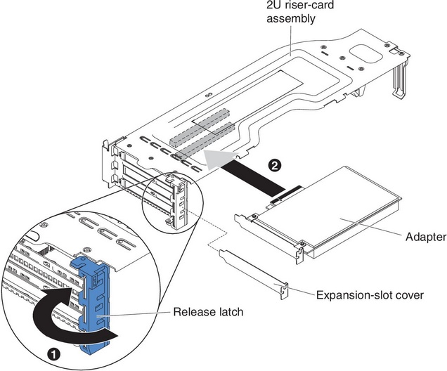
- For 2U PCI riser-card assembly 1
- Rotate the retention latch to the open position. Insert the adapter into the PCI riser-card assembly, aligning the edge connector on the adapter with the connector on the PCI riser-card assembly. Press the edge of the connector firmly into the PCI riser-card assembly. Make sure that the adapter snaps into the PCI riser-card assembly securely.
- Rotate the retention latch to the close position. Make sure the retention latch engages the adapter securely; then, push in the release pin to lock the retention latch in place.
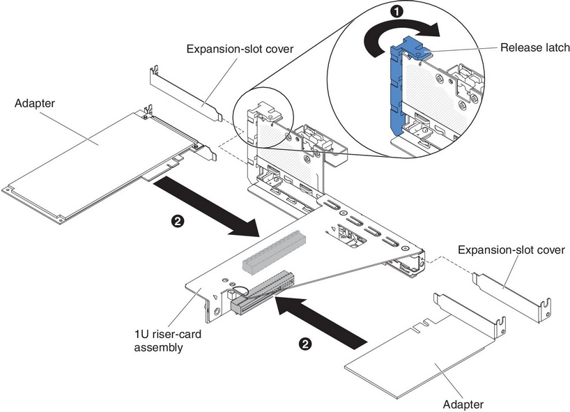
- For 1U PCI riser-card assembly 1:
- Rotate the retention latch to the open position. Insert the adapter into the PCI riser-card assembly, aligning the edge connector on the adapter with the connector on the PCI riser-card assembly. Press the edge of the connector firmly into the PCI riser-card assembly. Make sure that the adapter snaps into the PCI riser-card assembly securely.
- Rotate the retention latch to the close position. Make sure the retention latch engages the adapter securely.
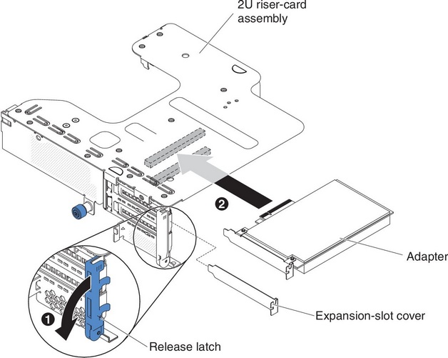
- For 2U PCI riser-card assembly 2:
- Rotate down the retention latch to the open position. Insert the adapter or ServeRAID adapter into the riser-card assembly, aligning the edge connector on the adapter with the connector on the riser-card assembly. Press the edge of the connector firmly into the riser-card assembly. Make sure that the adapter snaps into the riser-card assembly securely.
- Rotate the retention latch to the close position. Make sure the retention latch engages the adapter securely.
- For 1U PCI riser-card assembly 2:NoteFor 1U PCI riser-card assembly 2, it only supports ServeRAID adapters (see
Installing a ServeRAID adapter on the PCI riser-card assembly).
- For 2U PCI riser-card assembly 1
If you have other devices to install or remove, do so now. Otherwise, go to Completing the installation.
Give documentation feedback