Installing an additional microprocessor and heat sink
Use this information to install an additional microprocessor and heat sink.
The following notes describe the type of microprocessor that the server supports and other information that you must consider when you install a microprocessor:
- The server supports Intel scalable multi-core microprocessors which are designed for the LGA 1356 socket. Scalable up to eight cores with an integrated memory controller, quick-path interconnect and shared last cache. See the Lenovo ServerProven website for a list of supported microprocessors.
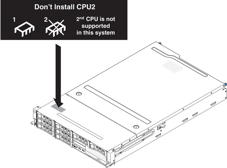
- If you are installing microprocessor Intel E5-1403, E5-1407 or Intel E5-1410, attach the microprocessor information label on the front of the server as the following illustration shows.
- Both microprocessors must have the same QuickPath Interconnect (QPI) link speed, integrated memory controller frequency, core frequency, power segment, cache size, and type.
- Read the documentation that comes with the microprocessor to determine whether you must update the server firmware for the server. To download the most current level of server firmware and many other code updates for your server, complete the following steps:
- Go to the Lenovo Support Portal.
- Under Product support, click System x.
- Under Popular links, click Software and device drivers.
- Click System x3630 M4 to display the matrix of downloadable files for the server.
- (Optional) Obtain an SMP-capable operating system. For a list of supported operating systems and optional devices, see the Lenovo ServerProven website.
- To order additional microprocessor optional devices, contact your Lenovo marketing representative or authorized reseller.
- The microprocessor speeds are automatically set for this server; therefore, you do not have to set any microprocessor frequency-selection jumpers or switches.
- If you have to replace a microprocessor, call for service.
- If the thermal-grease protective cover (for example, a plastic cap or tape liner) is removed from the heat sink, do not touch the thermal grease on the bottom of the heat sink or set down the heat sink.
- Do not remove the first microprocessor from the system board to install the second microprocessor.
Attention
- A startup (boot) microprocessor must always be installed in microprocessor socket 1 on the system board.
- To ensure correct server operation when you install an additional microprocessor, use microprocessors that are compatible and install at least one DIMM in a DIMM connector for microprocessor 2.
To install an additional microprocessor, complete the following steps:
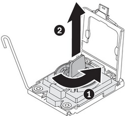
- Open the microprocessor bracket frame by lifting up the tab on the top edge. Keep the bracket frame in the open position.
 AttentionDo not touch the connectors on the microprocessor and the microprocessor socket.
 - Install the microprocessor:
- Align the holes on the microprocessor installation tool with the screws on the microprocessor bracket, then place the microprocessor installation tool down over the microprocessor. Twist the handle clockwise to attach the tool to the microprocessor.
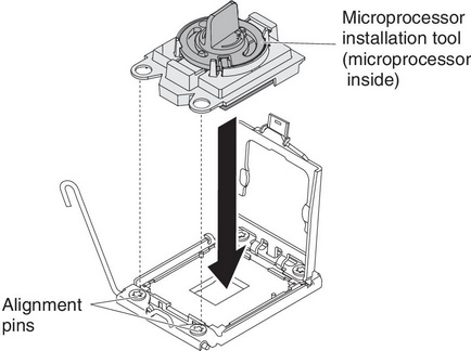
- Twist the handle on the microprocessor tool counterclockwise to insert the microprocessor into the socket.
 Attention
- Do not press the microprocessor into the socket.
- Do not touch exposed pins of the microprocessor socket. The pins on the socket are fragile. Any damage to the pins may require replacing the system board.
- Make sure that the microprocessor is oriented and aligned correctly in the socket before you try to close the microprocessor retainer.
- Do not touch the thermal material on the bottom of the heat sink or on top of the microprocessor. Touching the thermal material will contaminate it and destroys its even distribution. If the thermal material on the microprocessor or heat sink becomes contaminated, you must replace the thermal grease.
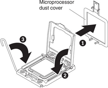
- Close the microprocessor release lever by pressing down on the end, moving it back under the release lever holder underneath the microprocessor bracket.
- Align the holes on the microprocessor installation tool with the screws on the microprocessor bracket, then place the microprocessor installation tool down over the microprocessor. Twist the handle clockwise to attach the tool to the microprocessor.
- Install a heat sink on the microprocessor:AttentionDo not touch the thermal grease on the bottom of the heat sink or set down the heat sink after you remove the plastic cover. Touching the thermal grease will contaminate it. If the thermal grease is contaminated, call Lenovo service and support to request a replacement thermal grease kit. For information about installing the replacement thermal grease, see
Thermal grease. - Align the screw holes on the heat sink with the holes on the system board; then, place the heat sink on the microprocessor with the thermal-grease side down.
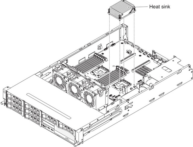
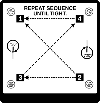
- Press firmly on the captive screws and tighten them with a screwdriver. The follow illustration shows the sequence in tightening the screws, which is also shown on top of the heat sink. Begin with the screw labeled as "1", then "2", "3" and finally "4". If possible, each screw should be rotated two full rotations at a time. Repeat until the screws are tight. Do not overtighten the screws by using excessive force. If you are using a torque wrench, tighten the screws to 8.5 Newton-meters (Nm) to 13 Nm (6.3 foot-pounds to 9.6 foot-pounds).
- Align the screw holes on the heat sink with the holes on the system board; then, place the heat sink on the microprocessor with the thermal-grease side down.
If you have other devices to install or remove, do so now. Otherwise, go to Completing the installation.
Give documentation feedback