Installing an optional hot-swap rear hard disk drive cage
Use this information to install an optional hot-swap rear hard disk drive cage into the server.

Note
The two fan slots in the rear hot-swap hard disk drive cage and Fan connector 4 / Fan connector 5 on the system board are currently reserved for future possible use with 15K rpm hard disk drives.
To install the optional rear hot-swap hard disk drive cage, complete the following steps:
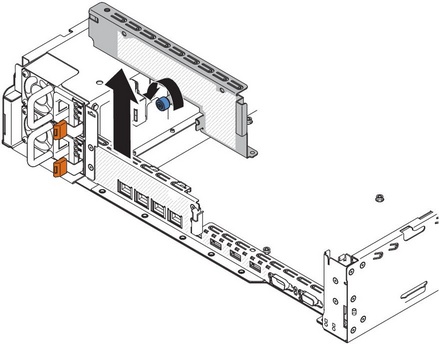
- If a drive filler cage is installed in the chassis, loosen the screw that secures the drive filler cage to the chassis; then, rotate the drive filler clockwise and remove the drive filler out of the bay from the server. Go to step 8.NoteIf 2U PCI riser-card assemblies are installed in the server, go to step 5.
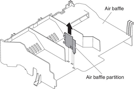
- If an air baffle partition is installed in the air baffle, remove it from the air baffle.
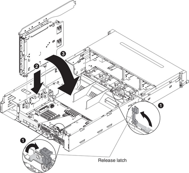
- Align the two moveable levers of the rear hard disk drive cage with the two chassis support brackets. Slide the cage into the chassis support brackets until it firmly sits into place 2 . Then, rotate the cage inward until it firmly sits into place 3 .
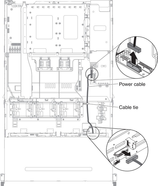
- Remove the power cable that currently connects the hot-swap hard disk drive backplane in the server to the power-paddle card.
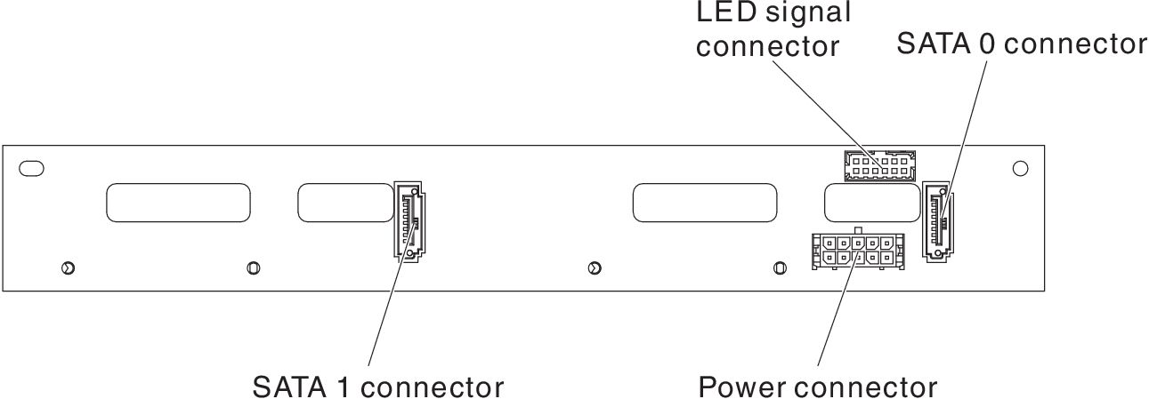
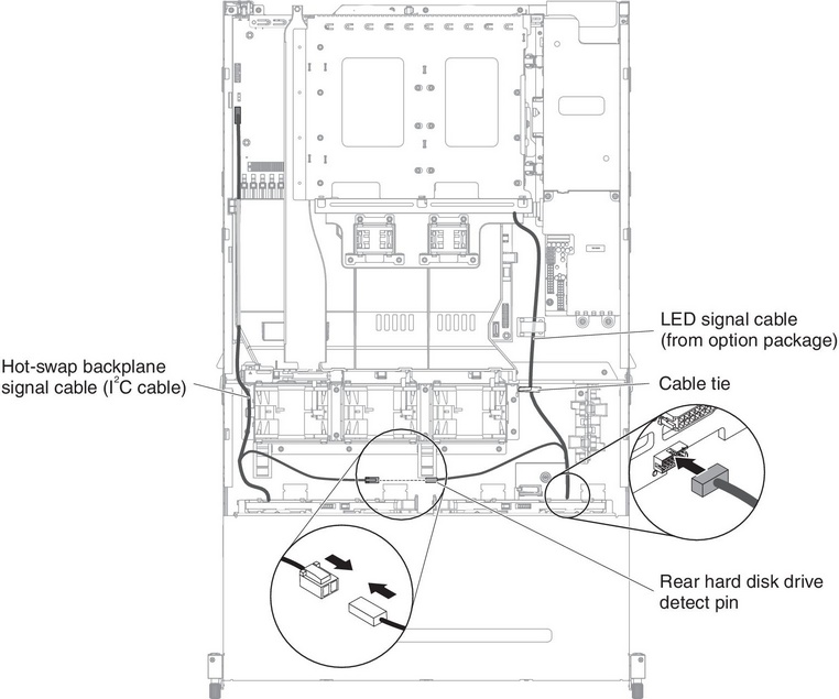
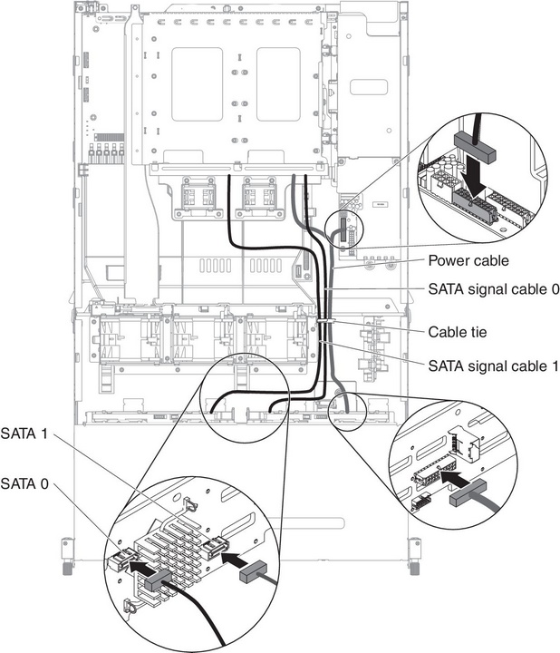
- Connect the LED signal, SATA signal and power cables to the hot-swap backplane from the option package.
- Find the rear hard disk drive detect pin of the hot-swap backplane signal (I2C) cable located near the system fan cage; then, connect with the rear hard disk drive detect pin of the LED signal cable from the option package.
- Connect the other end of the SATA signal and power cables to the power paddle card and hot-swap hard disk drive backplane in the server. Make sure the labels of both connectors are matched.
 NoteMake sure the cables are routed in the proper locations without blocking the airflow. It is recommended to press all the cables downwards to make the cable routing easier. Secure the cables with any cable retention clips.
If you have other devices to install or remove, do so now. Otherwise, go to Completing the installation.
Give documentation feedback