Installing an additional microprocessor and heat sink
Use this information to install an additional microprocessor and heat sink.
The following notes describe the type of microprocessor that the server supports and other information that you must consider when you install a microprocessor and heat sink:
- Be extremely careful when handling the microprocessor, the microprocessor socket contacts are very fragile.
- Do not use any tools or sharp objects to lift the locking levers on the microprocessor socket. Doing so might result in permanent damage to the system board.
- Do not touch the microprocessor contacts. Contaminants on the microprocessor contacts, such as oil from your skin, can cause connection failures between the contacts and the socket.
- Do not allow the thermal grease on the microprocessor and heat sink to come in contact with anything. Contact with any surface can compromise the thermal grease and the microprocessor socket.
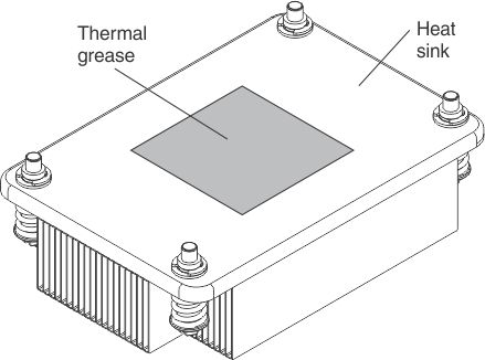
- If the thermal-grease protective cover (for example, a plastic cap or tape liner) is removed from the heat sink, do not touch the thermal grease on the bottom of the heat sink or set down the heat sink. For more information, see Thermal grease.NoteRemoving the heat sink from the microprocessor destroys the even distribution of the thermal grease and requires replacing the thermal grease.
- Each microprocessor socket must always contain either a socket cover or a microprocessor and heat sink.
- When installing multiple microprocessors, open one microprocessor socket at a time to avoid damaging other microprocessor socket contacts.
- When you handle static-sensitive devices, take precautions to avoid damage from static electricity. For details about handling these devices, see Handling static-sensitive devices.
- The server base system board supports two microprocessors. The optional microprocessor and memory expansion tray provides two additional microprocessor slots plus 24 additional DIMM connectors. The server supports up to four Intel Xeon four-core, six-core, eight-core, ten core, or twelve-core microprocessors (depending on your model) with the microprocessor and memory expansion tray installed. To confirm that the server supports the microprocessor, see Lenovo ServerProven website for a list of supported microprocessors.
- A microprocessor air baffle must be installed whenever the two DIMM connectors closest to the microprocessor (on the left and the right) are empty. For example, when DIMM connectors 6 and 7 on the system board are empty, a microprocessor air baffle must be installed on microprocessor 1. This is applicable for all microprocessors.
- Microprocessors 3 and 4 must be installed as a pair on the optional microprocessor and memory expansion tray.NoteThe server does not support a configuration of three microprocessors. You must install one, two, or four microprocessors in the server.
- Do not mix four-core, six-core, eight-core, ten core or twelve-core microprocessors in the same server.
- The microprocessor options supported are limited by the capacity and capability of the server. Any additional microprocessor that you install must have the same specifications as the microprocessors that came with the server.
- You must always have a microprocessor in socket 1 on the system board.
- When one microprocessor is installed, the microprocessor air baffle, the DIMM air baffle, or the microprocessor and memory expansion tray must be installed to provide proper system cooling.
- When you install an additional microprocessor, you must also install additional memory. See Non-mirroring (independent mode), Memory mirroring, and Memory sparing for details about DIMM installation sequence.
- To ensure proper server operation when you install an additional microprocessor, use microprocessors that have the same QuickPath Interconnect (QPI) link speed, integrated memory controller frequency, core frequency, power segment, internal cache size, and type.
- Installing microprocessors of different stepping levels within the same server is supported.
- When you install microprocessors with different stepping levels within the same server, you do not have to install the microprocessor with the lowest stepping level and features in microprocessor socket 1.
- The components in the server dictate the number of microprocessors that you must install to support the components. Failure to adhere to the following information will affect the system performance and functionality:
Table 1. The components supported by each microprocessor Number of microprocessors Components the server can support with the number of microprocessor(s) installed Microprocessor 1 - Onboard LSI SAS controller
- ML2 adapter
- PCIe slots 6, 7, and 8
Microprocessor 2 - PCIe slots 1, 2, 3, 4, and 5
Microprocessor 3 and 4 (these must be installed as a pair) - A fully-populated server
- The server supports microprocessor failover support. For example, if two microprocessors are installed and microprocessor 1 fails, the server will switch to microprocessor 2 until the server is serviced. To ensure that the microprocessor failover support works correctly, do the following:
- Make sure that microprocessor 1 and microprocessor 2 have valid boot devices and paths. That is, an Ethernet controller or a SAS controller must be installed in slots 1, 2, 3, 4, or 5 to boot from microprocessor 2.
- Make sure that the boot order in the Setup utility is set up so that microprocessor 1 and microprocessor 2 boot devices are in the boot order.
- The microprocessor voltage regulator modules are integrated on the system board and the microprocessor and memory expansion tray.
- If you have to replace a microprocessor, you must call for service.
- Read the documentation that comes with the microprocessor, so that you can determine whether you have to update the server firmware. To download the latest level of the server firmware and other code updates for your server, go to Lenovo Data Center Support.
- To order an additional optional microprocessor, contact your Lenovo sales representative or Lenovo reseller.
- When you order a microprocessor option kit, it comes with a microprocessor installation tool that you must use to install the microprocessor. The microprocessor installation tool comes with the microprocessor and a protective cover on the bottom of the microprocessor tool.
- The following table shows the DIMM connectors on the system board and the microprocessor and memory expansion tray that are associated with each microprocessor.
Table 2. DIMM connectors associated with each microprocessor Microprocessor Location DIMM connectors associated with the microprocessor Microprocessor 1 System board 1 through 12 Microprocessor 2 System board 13 through 24 Microprocessor 3 Microprocessor and memory expansion tray 25 through 36 Microprocessor 4 Microprocessor and memory expansion tray 37 through 48 NoteDIMMs 1 through 12 are solely associated with microprocessor 1. Microprocessor 2 has access to DIMMs 1 through 12, but access is through microprocessor 1. This is important if load balancing is a necessity for your operating system or software load.
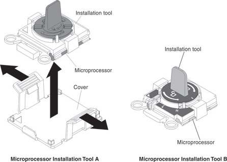
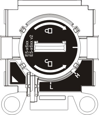
There are two types of microprocessor installation tools. The tools are similar in function and design; but, have a major difference:
- Installation Tool A has one setting for installing one size of microprocessor that supports E5-26xx and E5-46xx microprocessors.
- Installation Tool B supports E5-26xx, E5-46xx, E5-26xx v2, and E5-46xx v2 microprocessors. Installation Tool B has two settings for installing two different sizes of microprocessors. The settings on Tool B are:
L
for smaller low core microprocessorsH
for larger high core microprocessors
Microprocessor Installation Tools A and B are shown in the next illustration.
To install an additional microprocessor and heat sink, complete the following steps:
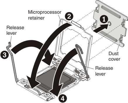
- Open the microprocessor socket release levers and retainer:
- Open the microprocessor retainer by lifting up on the microprocessor retainer tab.
Open the microprocessor socket release levers and retainer in the order that is shown.
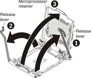
- Open the microprocessor retainer by lifting up on the microprocessor retainer tab.
- Install the microprocessor in the microprocessor socket:
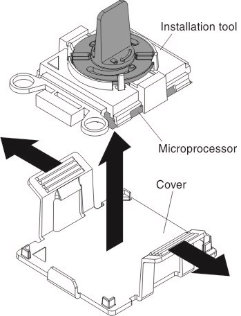
- Release the sides of the microprocessor protective cover on the bottom of the microprocessor and carefully remove the cover from the installation tool.NoteThe microprocessor is preinstalled on the installation tool.
- Carefully align the microprocessor installation tool with the microprocessor socket. The installation tool rests flush on the socket only if it is properly aligned.
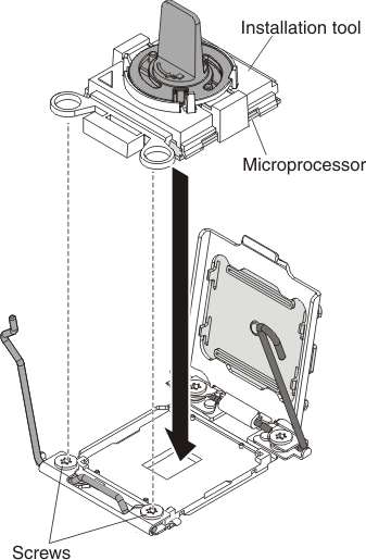
- Install the microprocessor using the appropriate instructions for your installation tool:
- If using Installation Tool A, twist the handle on the microprocessor tool assembly counterclockwise to the open position to insert the microprocessor into the socket; then, lift the installation tool out of the socket.
- If using Installation Tool B, twist the handle of the installation tool assembly counterclockwise until the microprocessor is inserted into the socket; then, lift the installation tool out of the socket.
The next illustration shows Installation Tool B with the tool handle in the open position.
Attention- Do not press the microprocessor into the socket.
- Make sure that the microprocessor is aligned correctly in the socket before you try to close the microprocessor retainer.
- Do not touch the thermal grease on the bottom of the heat sink or on top of the microprocessor. Touching the thermal grease will contaminate it.
- Release the sides of the microprocessor protective cover on the bottom of the microprocessor and carefully remove the cover from the installation tool.
- Close the microprocessor retainer and release levers:
- Carefully close the microprocessor release levers to the closed position to secure the microprocessor in the socket. Make sure that you close the release lever on the left first; then, close the release lever on the right.Close the microprocessor retainer and release levers in the order shown.
 Attention
- If you are installing a new heat sink, do not set down the heat sink after you remove the plastic cover.
- Do not touch the thermal grease on the bottom of the heat sink after you remove the plastic cover. Touching the thermal grease will contaminate it. See Thermal grease for more information.
- Carefully close the microprocessor release levers to the closed position to secure the microprocessor in the socket. Make sure that you close the release lever on the left first; then, close the release lever on the right.
- Install the heat sink that came with the microprocessor:
- Remove the plastic protective cover from the bottom of the heat sink.
- Align the captive screws on the heat sink with the holes on the heat-sink retention module.
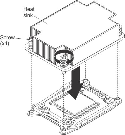
- Remove the plastic protective cover from the bottom of the heat sink.
If you have other devices to install, do so now. Otherwise, go to Completing the installation.
Give documentation feedback