Installing the 8x1.8-inch hot-swap drive backplane assembly
Use this information to install the 8x1.8-inch hot-swap drive backplane assembly.
Note
- For more information about connecting the SAS signal cables to the drive backplane, see Connecting the SAS cables.
- When you install a 8x1.8-inch drive backplane assembly, the drive IDs that are indicated on the server front bezel will no longer be valid. Use the drive labels that come with the backplane to renumber the drive IDs on the bezel.
- For more information about drive IDs, see Drive IDs. For more information about the supported drive backplane configurations, see Supported SAS/SATA drive backplane configurations.
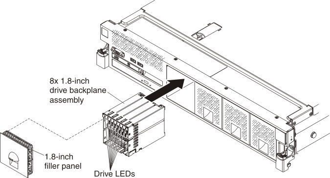
To install the 8x1.8-inch hot-swap drive backplane assembly, complete the following steps:
- Align the backplane assembly with the backplane bay in which you are installing the assembly.
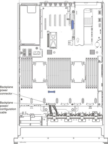
- Connect the combination power/configuration cable end to the power and configuration connectors on the backplane assembly; then, connect the power connector on the other end of the cable to the backplane power connector on the system board. See the following cabling illustration.NoteYou can connect the cables to the backplane before you install the backplane onto the cage or you can connect the cables after you install the backplane, if that is easier for you.
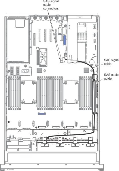
- Route the signal cables through the SAS cable guide and connect the signal cables to the backplane assembly and to the adapter or the system board.
If you have other devices to install or remove, do so now. Otherwise, go to Completing the installation.
Give documentation feedback