LEDs and buttons on the front I/O module
The front I/O module of the server provides control buttons, connectors, and LEDs.
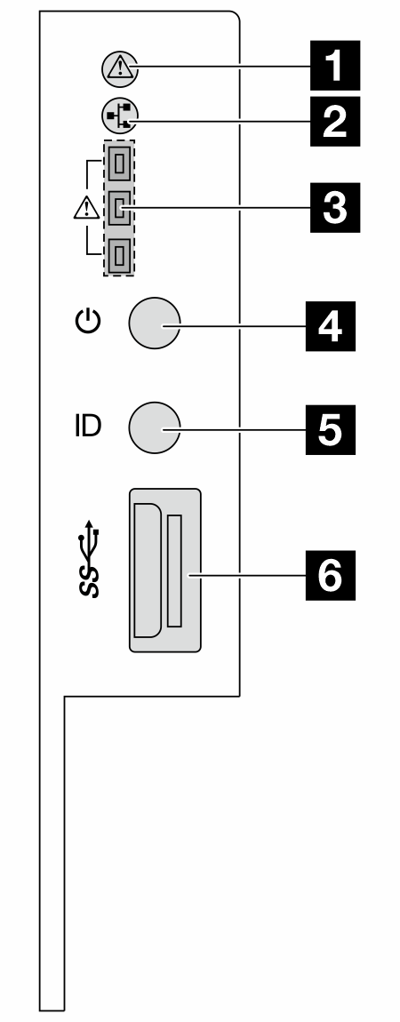
| 1 System health LED | 2 Network activity LED |
| 3 Tray 1/2/3 error LEDs | 4 Power button with power status LED |
| 5 UID button with UID LED | 6 USB 3.2 Gen1 (5 Gbps) connector |
1 System health LED
The system health LED helps determine if there are any system errors. There is another system health LED on DC-SCM on the rear, see LEDs and buttons on Datacenter Secure Control Module (DC-SCM).
| Status | Color | Description |
|---|---|---|
| Solid on | Yellow | A warning error has been detected on the server. Check the BMC event log to determine the exact cause of the error. |
| Blinking | A critical error has been detected on the server. | |
| Off | / | The server is off or the server is on and is working normally. |
2 Network activity LED
When an OCP module is installed, the network activity LED on the front I/O module helps you identify the network connectivity and activity. If no OCP module is installed, this LED is off.
| Status | Color | Description |
|---|---|---|
| Solid on | Green | The server is connected to a network. |
| Blinking (4Hz) | The network is connected and active. | |
| Off | / | The server is disconnected from the network. Note If the network activity LED is off when an OCP module is installed, check the network ports in the rear of your server to determine which port is disconnected. |
3 Tray 1/2/3 error LEDs
The server comes with three tray error LEDs to help identify the status of front drives connected to front backplanes from the top down.
| Status | Color | Description |
|---|---|---|
| Solid on | Red | At least one front drive is not connected to the backplane correctly, or the backplane is not working normally. |
| Off | / | All drives and backplanes work normally. |
4 Power button with power status LED
| Status | Color | Description |
|---|---|---|
| Solid on | Green | Power on. |
| Slow blinking (about one flash per second) | Power off, and the server is ready to be powered on (standby state). | |
| Fast blinking (about four flashes per second) | Power fault, or the server is waiting for BMC power permission to be ready. | |
| Off | None | There is no ac power applied to the server. |
5 UID button with UID LED
Use this UID button and the blue UID LED to visually locate the server. There is another UID LED on DC-SCM on the rear, see LEDs and buttons on Datacenter Secure Control Module (DC-SCM).
Each time you press the UID button, the state of both the UID LEDs changes. The LEDs can be changed to on, blinking, or off. Press the UID button down and hold for five seconds, you can reset BMC.
You can also use BMC or a remote management program to change the state of the UID LEDs to assist in visually locating the server among other servers.
6 USB 3.2 Gen 1 (5Gbps) ports
The USB 3.2 Gen 1 (5Gbps) connectors are direct connect interfaces (DCIs) for debugging, which can be used to attach a USB-compatible device, such as a USB keyboard, USB mouse, or USB storage device.