LEDs and buttons on Datacenter Secure Control Module (DC-SCM)
The Datacenter Secure Control Module (DC-SCM) provides controls, connectors, and LEDs.
Connectors, LEDs and buttons on the front of DC-SCM
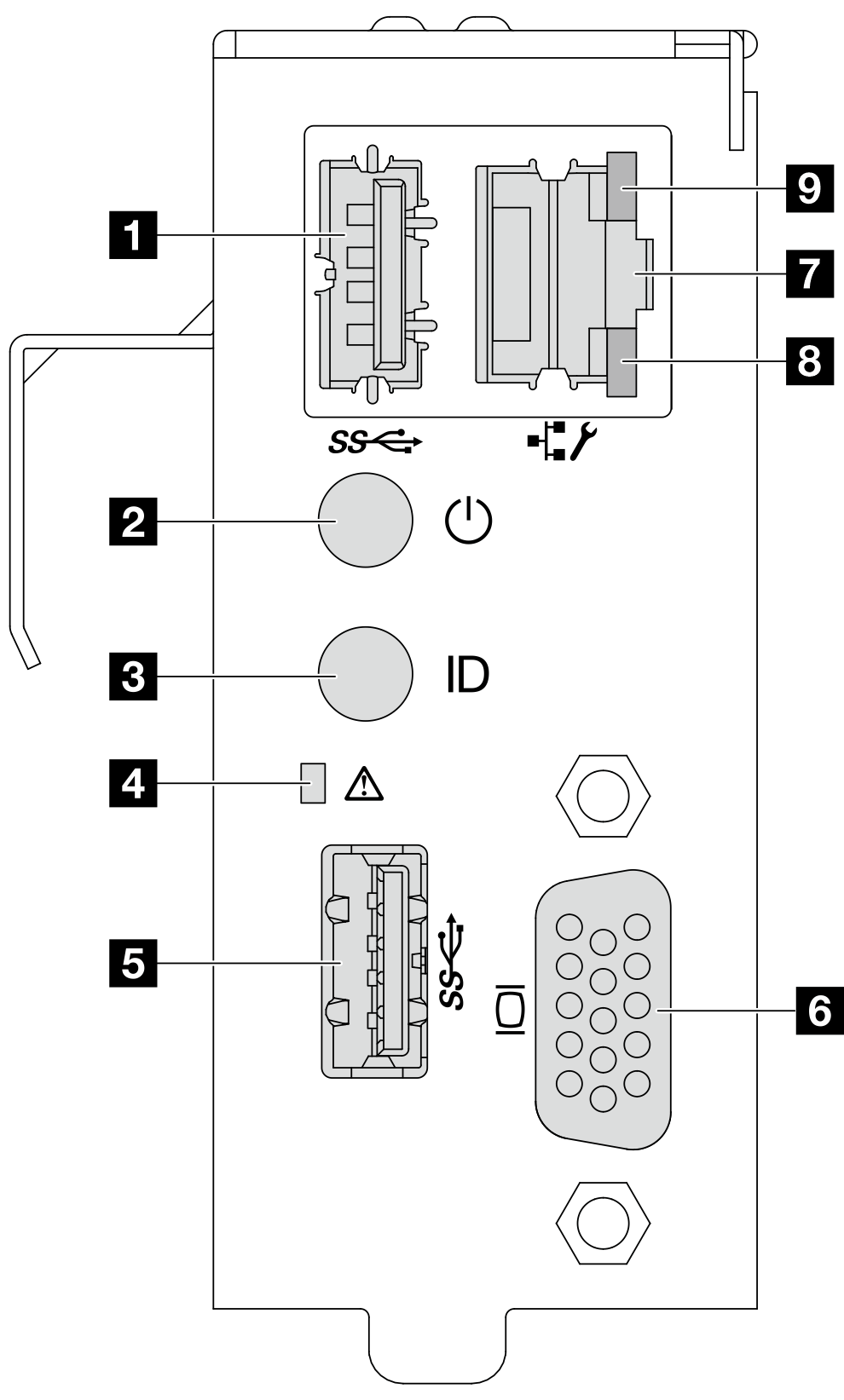
| 1 USB 3.2 Gen 1 (5Gbps) port 1 | 2 Power button and power status LED |
| 3 UID button and UID LED | 4 System health LED |
| 5 USB 3.2 Gen 1 (5Gbps) port 2 | 6 VGA port |
| 7 BMC system management port (RJ-45) | 8 Ethernet port activity LED |
| 9 Ethernet port link LED |
1 5 USB 3.2 Gen 1 (5Gbps) ports
The USB 3.2 Gen 1 (5Gbps) connectors are direct connect interfaces (DCIs) for debugging, which can be used to attach a USB-compatible device, such as a USB keyboard, USB mouse, or USB storage device.
2 Power button with power status LED
| Status | Color | Description |
|---|---|---|
| Solid on | Green | Power on. |
| Slow blinking (about one flash per second) | Green | Power off, and the server is ready to be powered on (standby state). |
| Fast blinking (about four flashes per second) | Green | Power fault, or the server is waiting for BMC power permission to be ready. |
| Off | None | There is no ac power applied to the server. |
3 UID button with UID LED
Use this UID button and the blue UID LED to visually locate the server. There is another UID button with UID LED on front I/O module on the front, see LEDs and buttons on the front I/O module.
Each time you press the UID button, the state of both the UID LEDs changes. The LEDs can be changed to on, blinking, or off. Press the UID button down and hold for five seconds, you can reset BMC.
You can also use BMC or a remote management program to change the state of the UID LEDs to assist in visually locating the server among other servers.
4 System health LED
The system health LED helps determine if there are any system errors. There is another system health LED on front I/O module on the front, see LEDs and buttons on the front I/O module.
| Status | Color | Description |
|---|---|---|
| Solid on | Yellow | A warning error has been detected on the server. Check the BMC event log to determine the exact cause of the error. |
| Blinking | A critical error has been detected on the server. | |
| Off | / | The server is off or the server is on and is working normally. |
6 VGA port
The VGA port on the rear of the server can be used to attach a high-performance monitor, a direct-drive monitor, or other devices that use a VGA connector.
7 BMC system management port (RJ-45)
The BMC system management port can be used to attach an Ethernet cable to manage the baseboard management controller (BMC).
8 9 LEDs on BMC system management port
| LED | Description |
|---|---|
| 8 Ethernet port activity LED | Use this green LED to distinguish the network activity status:
|
| 9 Ethernet port link LED | Use this LED to distinguish the network connectivity status:
|
LEDs and a connector on the side of DC-SCM
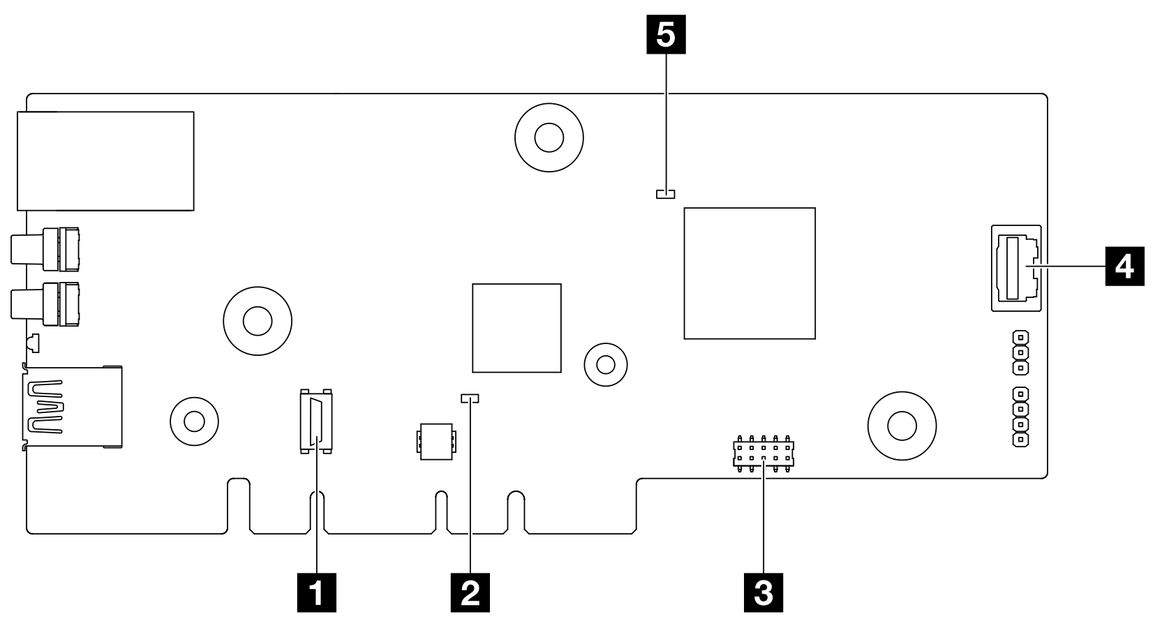
1 TPM connector
The connector is provided for TPM utilisation.
2 CPLD heartbeat LED (Green) 5 BMC heartbeat LED (Green)
| Item | Description |
|---|---|
| 2 CPLD heartbeat LED (Green) | The CPLD heartbeat LED helps you identify the power and health status of the system board. There is another CPLD heartbeat LED on the front backplane, see Front backplane LEDs and rear drive LEDs.
|
| 5 BMC heartbeat LED (Green) | The BMC heartbeat LED helps you identify the BMC status.
|
3 Serial port connector
The connector is provided for serial port utilisation.
4 VGA port
Connected to the VGA port on the front of DC-SCM, the VGA port on the side can be used with a cable plugged in.