Installing a memory module
The following notes describe the types of DIMMs that the compute node supports and other information that you must consider when you install DIMMs.
- When you install or remove DIMMs, the compute node configuration information changes. When you restart the compute node, the system displays a message that indicates that the memory configuration has changed.
- The compute node supports only industry-standard double-data-rate 4 (DDR4), 1600, 1866, 2133, or 2400 MHz, PC4-12800, PC4-14900, PC4-17000, or PC4-19200 registered or load deduction, synchronous dynamic random-access memory (SDRAM) dual inline memory modules (DIMMs) with error correcting code (ECC). See the Lenovo ServerProven website for a list of supported memory modules for the compute node.
- The specifications of a DDR4 DIMM are on a label on the DIMM, in the following format.
gggggeRxff PC3v-wwwwwm-aa-bb-ccd
where:- ggggg is the total capacity of the DIMM (for example, 1 GB, 2 GB, or 4 GB)
- eR is the number of ranks
- 1R = single-rank
- 2R = dual-rank
- 4R = quad-rank
- xff is the device organization (bit width)
- x4 = x4 organization (4 DQ lines per SDRAM)
- x8 = x8 organization
- x16 = x16 organization
- v is the SDRAM and support component supply voltage (VDD)
- Blank = 1.2 V specified
- wwwww is the DIMM bandwidth, in MBps
- 12800 = 12.80 GBps (DDR4-1600 SDRAMs, 8-byte primary data bus)
- 14900 = 14.93 GBps (DDR4-1866 SDRAMs, 8-byte primary data bus)
- 17000 = 17.00 GBps (DDR4-2133 SDRAMs, 8-byte primary data bus)
- m is the DIMM type
- E = Unbuffered DIMM (UDIMM) with ECC (x72-bit module data bus)
- L = Load Reduction DIMM (LRDIMM)
- R = Registered DIMM (RDIMM)
- U = Unbuffered DIMM with no ECC (x64-bit primary data bus)
- aa is the CAS latency, in clocks at maximum operating frequency
- bb is the JEDEC SPD Revision Encoding and Additions level
- cc is the reference design file for the design of the DIMM
- d is the revision number of the reference design of the DIMM
NoteTo determine the type of a DIMM, see the label on the DIMM. The information on the label is in the format xxxxxnRxxx PC3v-xxxxxx-xx-xx-xxx. The numeral in the sixth numerical position indicates whether the DIMM is single-rank (n=1), dual-rank (n=2), or quad-rank (n=4). - The specifications of a DDR4 DIMM are on a label on the DIMM, in the following format.
- The following rules apply to DDR4 RDIMM speed as it relates to the number of RDIMMs in a channel (with microprocessors of Intel Xeon E5-26xx v4):
- When you install 1 RDIMM per channel, the memory runs at 2400 MHz
- When you install 2 RDIMMs per channel, the memory runs at 2400 MHz (down to 2133 MHz if the RDIMMs are 8 GB dual-rank)
- When you install 1 LRDIMM per channel, the memory runs at 2400 MHz
- When you install 2 LRDIMMs per channel, the memory runs at 2133 MHz
- All channels in a server run at the fastest common frequency
- Do not install registered and load reduction DIMMs in the same server
- The following rules apply to DDR4 RDIMM speed as it relates to the number of RDIMMs in a channel (with microprocessors of Intel Xeon E5-26xx v3):
- When you install 1 RDIMM per channel, the memory runs at 2133 MHz
- When you install 2 RDIMMs per channel, the memory runs at 2133 MHz
- When you install 1 LRDIMM per channel, the memory runs at 2133 MHz
- When you install 2 LRDIMMs per channel, the memory runs at 2133 MHz
- All channels in a server run at the fastest common frequency
- Do not install registered and load reduction DIMMs in the same server
- The maximum memory speed is determined by the combination of the microprocessor, DIMM speed, DIMM type, Operating Modes in UEFI settings, and the number of DIMMs installed in each channel.
- In two-DIMM-per-channel configuration, the compute node automatically operates with a maximum memory speed of up to 1600 MHz when the following condition is met:
- Two 1.35 V single-rank, dual-ranl, or quad-rank RDIMMs or LRDIMMs are installed in the same channel. In the Setup utility, Memory speed is set to Max performance and LV-DIMM power is set to Enhance performance mode. The 1.35 V UDIMMs, RDIMMs or LRDIMMs will function at 1.5 V.
- The compute node supports a maximum of 16 single-rank, dual--rank RDIMMs or 16 quad-rank LRIMMs.
- The following table shows an example of the maximum amount of memory that you can install using ranked DIMMs:
Table 1. Maximum memory installation using ranked DIMMs. Four column table documenting the total memory with different configurations.
Number of DIMMs DIMM type DIMM size Total memory 16 Single-rank RDIMM 4 GB 64 GB 16 Single-rank RDIMM 8 GB 128 GB 16 Dual-rank RDIMM 8 GB 128 GB 16 Dual-rank RDIMM 16 GB 256 GB 16 Quad-rank LRDIMM 32 GB 512 GB - The RDIMM options that are available for the compute node are 4 GB, 8 GB, and 16 GB. The compute node supports a minimum of 4 GB and a maximum of 256 GB of system memory using RDIMMs.
- The LRDIMM option that is available for the server is 32 GB. The compute node supports a minimum of 32 GB and a maximum of 512 GB of system memory using LRDIMMs
- A minimum of one DIMM must be installed for each microprocessor. For example, you must install a minimum of two DIMMs if the compute node has two microprocessors installed. However, to improve system performance, install a minimum of four DIMMs for each microprocessor.
- DIMMs in the compute node must be the same type to ensure that the compute node will operate correctly.
- When you install one quad-rank DIMM in a channel, install it in the DIMM connector furthest away from the microprocessor.
Note
- You can install DIMMs for microprocessor 2 as soon as you install microprocessor 2; you do not have to wait until all of the DIMM slots for microprocessor 1 are filled.
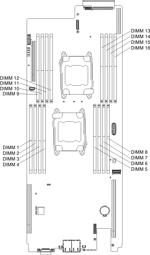
- DIMM slots 9-16 are reserved for microprocessor 2; thus, DIMM slots 9-16 are enabled when microprocessor 2 is installed.
The following illustration shows the location of the DIMM connectors on the system board.
Figure 1. DIMM connectors location
The following memory-channel configuration table shows the relationship between the processors, memory channels, and the DIMM connectors.
| Channels | Processor 1 – DIMM connectors | Processor 2 – DIMM connectors |
| Channel 0 | 7 and 8 | 9 and 10 |
| Channel 1 | 5 and 6 | 11 and 12 |
| Channel 2 | 1 and 2 | 15 and 16 |
| Channel 3 | 3 and 4 | 13 and 14 |
Give documentation feedback