Install a processor and heat sink
This task has instructions for installing an assembled processor and heat sink, known as a processor-heat-sink module (PHM). This task requires a Torx T30 driver. This procedure must be executed by a trained technician.
About this task
To avoid potential danger, make sure to read and follow the safety information.
Read Installation Guidelines and Safety inspection checklist to make sure that you work safely.
Prevent exposure to static electricity, which might lead to system halt and loss of data, by keeping static-sensitive components in their static-protective packages until installation, and handling these devices with an electrostatic-discharge wrist strap or other grounding system.
- Each processor socket must always contain a cover or a PHM. When removing or installing a PHM, protect the empty processor sockets with a cover.
- Do not touch the processor socket or processor contacts. Processor-socket contacts are very fragile and easily damaged. Contaminants on the processor contacts, such as oil from your skin, can cause connection failures.
- Do not allow the thermal grease on the processor or heat sink to come in contact with anything. Contact with any surface can compromise the thermal grease, rendering it ineffective. Thermal grease can damage components, such as the electrical connectors in the processor socket.
- Remove and install only one PHM at a time. If the system supports multiple processors, install the PHMs starting with the first processor socket.
- The heat sink, processor, and processor carrier for your system might be different from those shown in the illustrations.
- PHMs are keyed for the socket where they can be installed and for their orientation in the socket.
- See Lenovo ServerProven website for a list of processors supported for your server. All processors must have the same speed, number of cores, and frequency.
- Before you install a new PHM or replacement processor, update your system firmware to the latest level. See Update the firmware.
Go to Drivers and Software download website for ThinkSystem SD530 V3 to see the latest firmware and driver updates for your server.
Go to Update the firmware for more information on firmware updating tools.
| One-processor configuration | Two-processor configuration | |
| 185-watt or lower |
|
|
| Greater than 185-watt, less or equal to 205-watt |
|
|
| Greater than 205-watt |
|
|
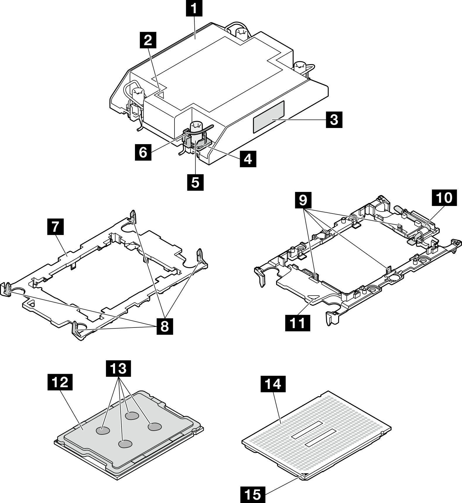
| 1 Heat sink | 9 Clips to secure processor in carrier |
| 2 Heat sink triangular mark | 10 Processor ejector handle |
| 3 Processor identification label | 11 Carrier triangular mark |
| 4 Nut and wire bail retainer | 12 Processor heat spreader |
| 5 Torx T30 nut | 13 Thermal grease |
| 6 Anti-tilt wire bail | 14 Processor contacts |
| 7 Processor carrier | 15 Processor triangular mark |
| 8 Clips to secure carrier to heat sink |
Procedure
- Install the processor in the new carrier.Note
- If you are replacing the processor and reusing the heat sink, use the new carrier that comes with the new processor.
- If you are replacing the heat sink and reusing the processor, and if the new heat sink comes with two processor carriers, make sure to use the same type of carrier as the one you discarded.
 Make sure the handle on the carrier is in the closed position.
 Align the processor on the new carrier so that the triangular marks align; then, insert the marked end of the processor into the carrier.
 Hold the inserted end of the processor in place; then, pivot the unmarked end of the carrier down and away from the processor.
 Press the processor and secure the unmarked end under the clip on the carrier.
 Carefully pivot the sides of the carrier down and away from the processor.
 Press the processor and secure the sides under the clips on the carrier.NoteTo prevent the processor from falling out of the carrier, keep the processor-contact side up and hold the processor-carrier assembly by the sides of the carrier.
Figure 2. Installation of the processor carrier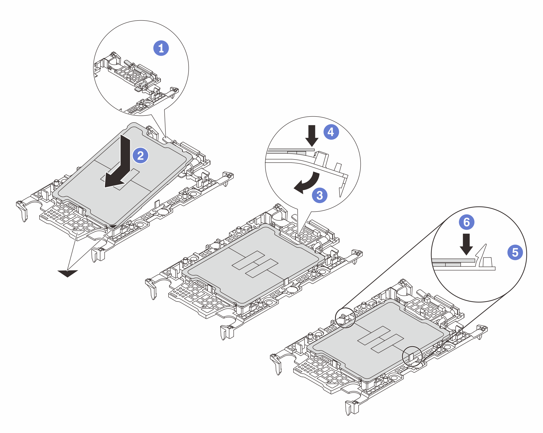
- Apply the thermal grease.
- If you are replacing the heat sink and reusing the processor, a new heat sink comes with thermal grease and you do not need to apply new thermal grease.NoteTo ensure the best performance, check the manufacturing date on the new heat sink and make sure it does not exceed two years. Otherwise, wipe off the existing thermal grease and apply new thermal grease.
- If you are replacing the processor and reusing the heat sink, do the following steps to apply thermal grease:
- If there is any old thermal grease on the heat sink, wipe off the thermal grease with an alcohol cleaning pad.
- Carefully place the processor and carrier in the shipping tray with the processor-contact side down. Make sure the triangular mark on the carrier is oriented in the shipping tray as shown below.
- Apply the thermal grease on the top of the processor with syringe by forming four uniformly spaced dots, while each dot consists of about 0.1 ml of thermal grease.
Figure 3. Thermal grease application with processor in shipping tray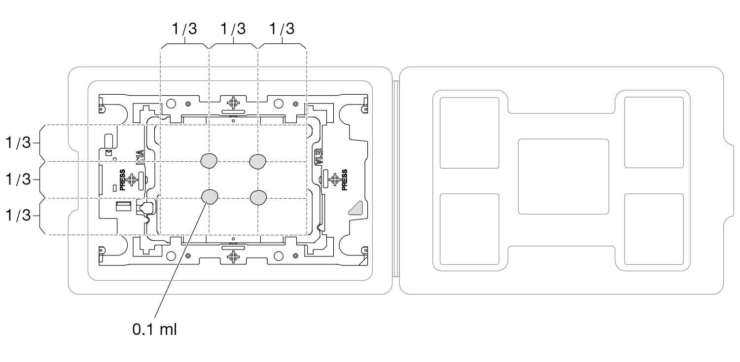
- If you are replacing the heat sink and reusing the processor, a new heat sink comes with thermal grease and you do not need to apply new thermal grease.
- Assemble the processor and heat sink.
- Visually inspect to make sure that there is no gap between the processor carrier and the heat sink.Figure 4. Assembling the PHM with processor in shipping tray
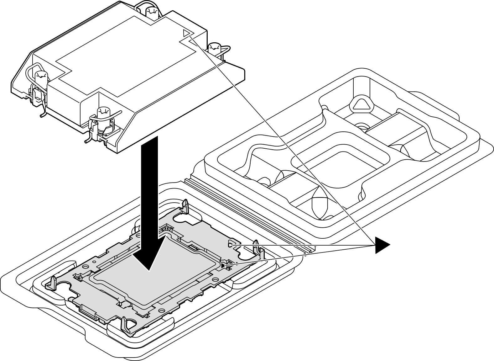
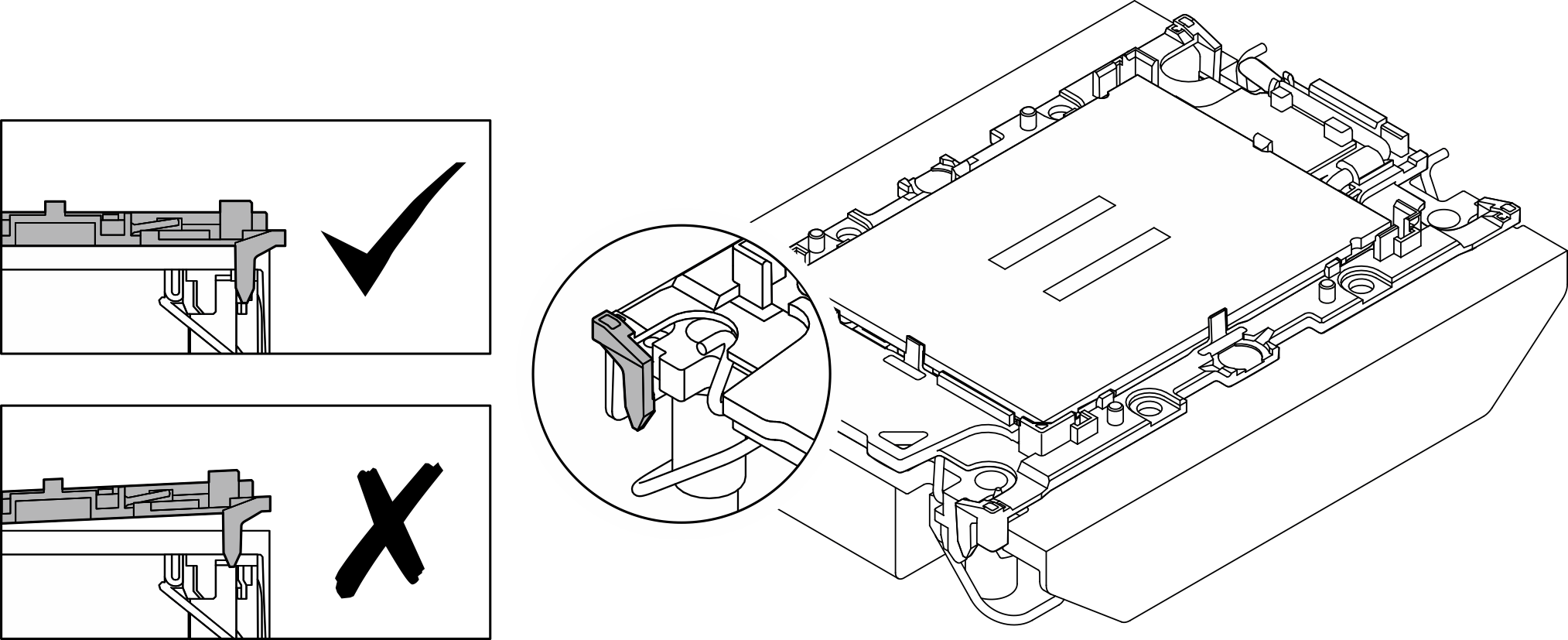
- Visually inspect to make sure that there is no gap between the processor carrier and the heat sink.
- Install the heat sink support bracket to the system board if performance heat sink is to be installed.
- Lower the heat sink support bracket onto the system board.
- Tighten the two screws to secure the heat sink support bracket.
Figure 5. Heat sink support bracket replacement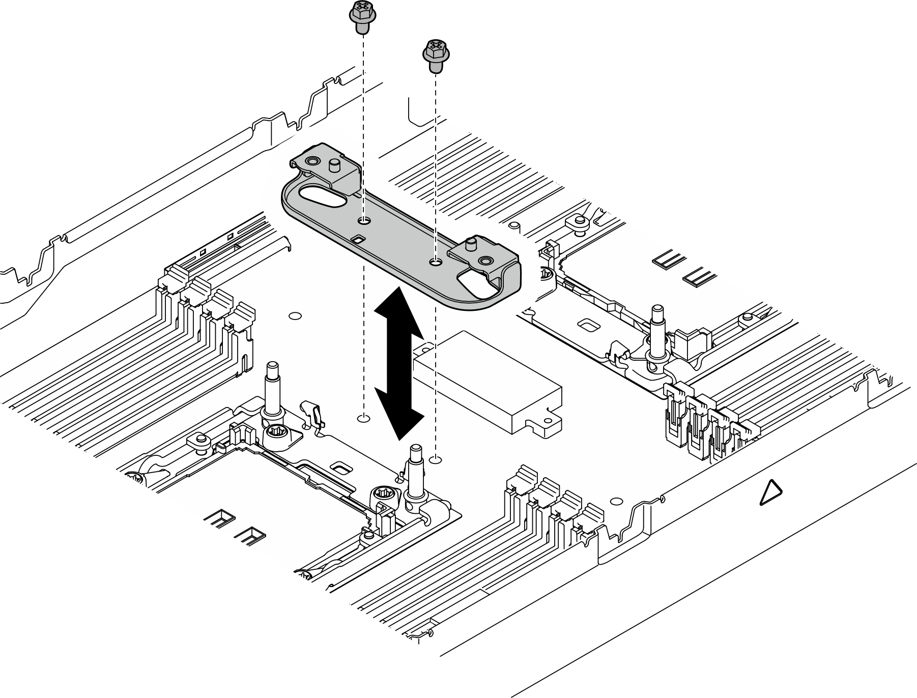
- For one-processor configuration, install the 1U standard heat sink or 1U performance heat sink into processor socket 1.Important
- Do not touch the contacts on the bottom of the processor.
- Keep the processor socket clean from any object to prevent possible damages.
- Rotate the anti-tilt wire bails inward.
- Align the triangular mark and four Torx T30 nuts on the PHM with the triangular mark and threaded posts of the processor socket; then, insert the PHM into the processor socket.
- Rotate the anti-tilt wire bails outward until they engage with the hooks in the socket.
- Fully tighten the Torx T30 nuts in the installation sequence shown on the heat-sink label. Tighten the screws until they stop; then, visually inspect to make sure that there is no gap between the screw shoulder beneath the heat sink and the processor socket.NoteFor reference, the torque required for the screws to be fully tightened/removed is 10+/- 2.0 lbf-in, 1.1+/- 0.2 N-m.AttentionTo prevent damage to components, make sure to follow the indicated tightening/loosening sequence.Figure 6. PHM location for one-processor configuration
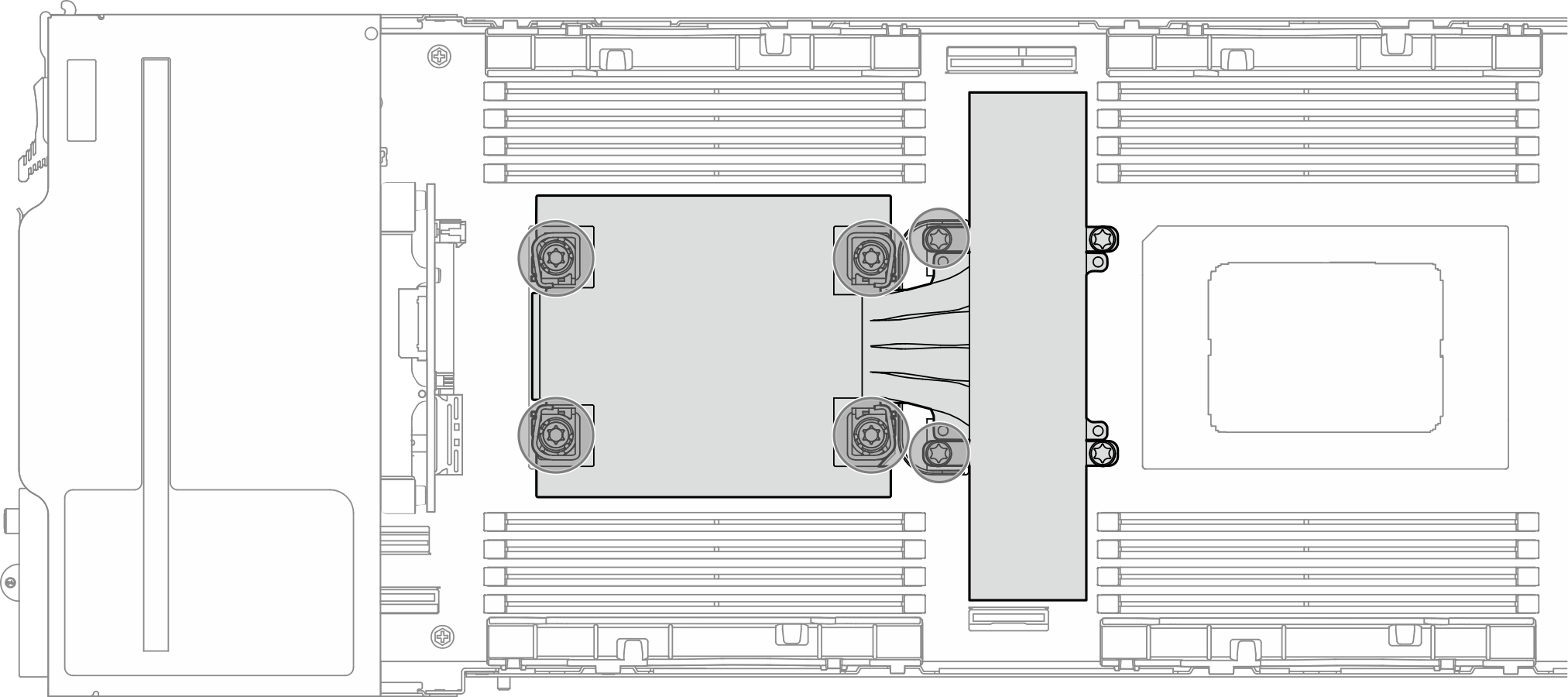 Figure 7. Installation of a 1U Performance PHM for one-processor configuration
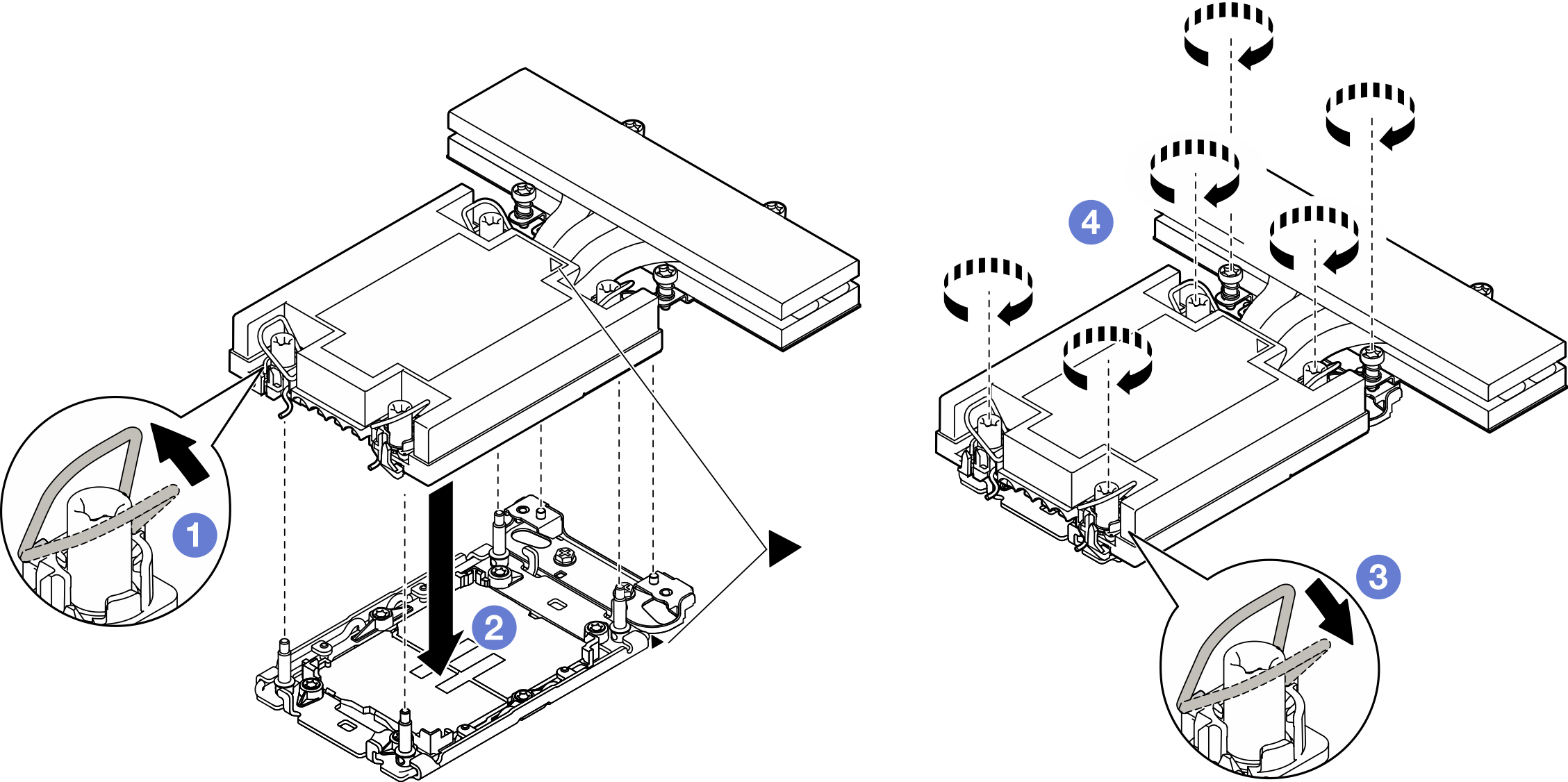 Figure 8. Installation of a 1U Standard PHM for one-processor configuration
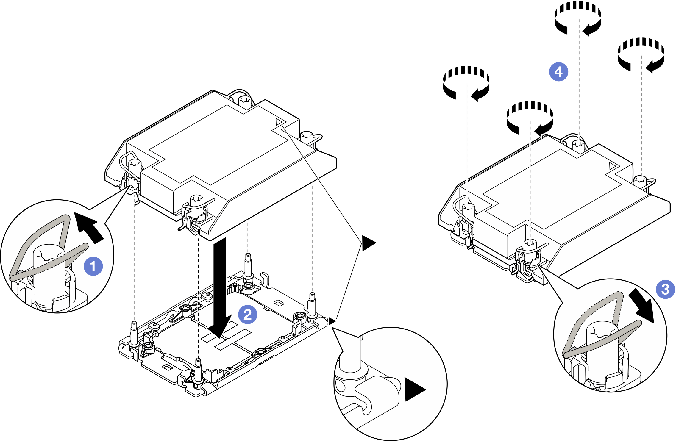
- For two-processor configuration, install the 1U standard heat sink into processor socket 1 and 1U performance heat sink into processor socket 2.Important
- Do not touch the contacts on the bottom of the processor.
- Keep the processor socket clean from any object to prevent possible damages.
- Rotate the anti-tilt wire bails inward.
- Align the triangular mark and four Torx T30 nuts on the PHM with the triangular mark and threaded posts of the processor socket; then, insert the PHM into the processor socket.
- Rotate the anti-tilt wire bails outward until they engage with the hooks in the socket.
- Fully tighten the Torx T30 nuts in the installation sequence shown on the heat-sink label. Tighten the screws until they stop; then, visually inspect to make sure that there is no gap between the screw shoulder beneath the heat sink and the processor socket.NoteFor reference, the torque required for the screws to be fully tightened/removed is 10+/- 2.0 lbf-in, 1.1+/- 0.2 N-m.AttentionTo prevent damage to components, make sure to follow the indicated tightening/loosening sequence.Figure 9. PHM location for two-processor configuration
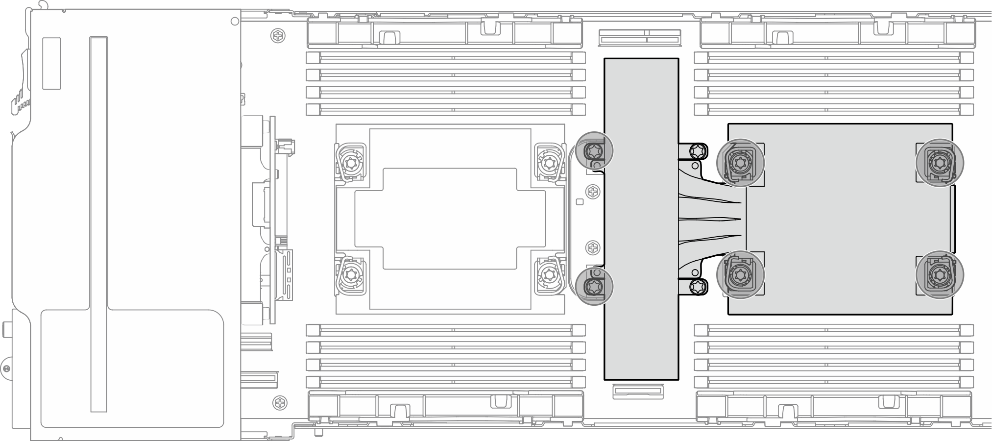 Figure 10. Installation of a 1U Standard PHM for two-processor configurationFigure 11. Installation of a 1U Performance PHM for two-processor configuration
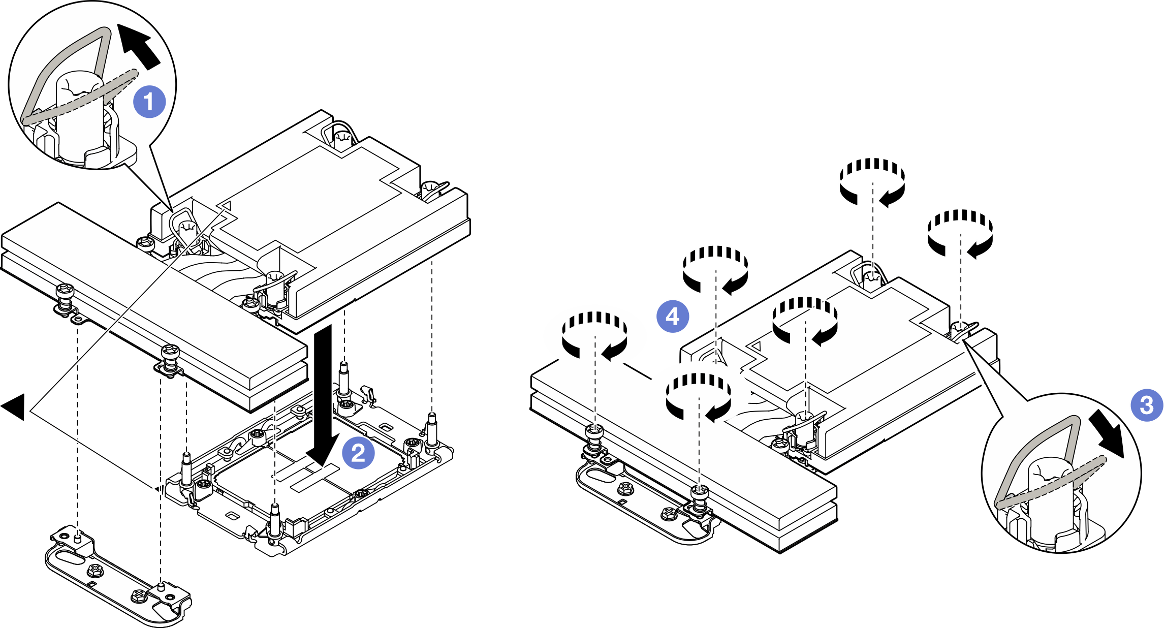
After you finish
- Make sure that all the required cables are routed and connected correctly; then, reinstall the top cover (see Install the top cover).
- Reinstall the node into the chassis (see Install a node to the chassis).
- Make sure that the required power supply units are installed and power cords are connected; then, power on the node (see Install a hot-swap power supply and Power on the node).
- Proceed to complete the parts replacement (see Complete the parts replacement).
To enable Intel® On Demand Suite to the new processor, or to transfer Intel® On Demand Suite from the defective processor to the new processor, refer to Enable Intel® On Demand.
Demo video