Install a PCIe riser assembly
Follow instructions in this section to install a PCIe riser assembly.
About this task
To avoid potential danger, make sure to read and follow the safety information.
Attention
Read Installation Guidelines and Safety inspection checklist to make sure that you work safely.
Touch the static-protective package that contains the component to any unpainted metal surface on the node and chassis; then, take the component out of the package and place it on a static-protective surface.
Procedure
- If the PCIe riser card is not installed in the riser cage, install it now.
- Align the screw holes of the PCIe riser card with the corresponding holes on the riser cage; then, insert the PCIe riser card into place.
- Tighten the screws to secure the PCIe riser card to the PCIe riser cage.
Figure 1. Replacement of the PCIe riser card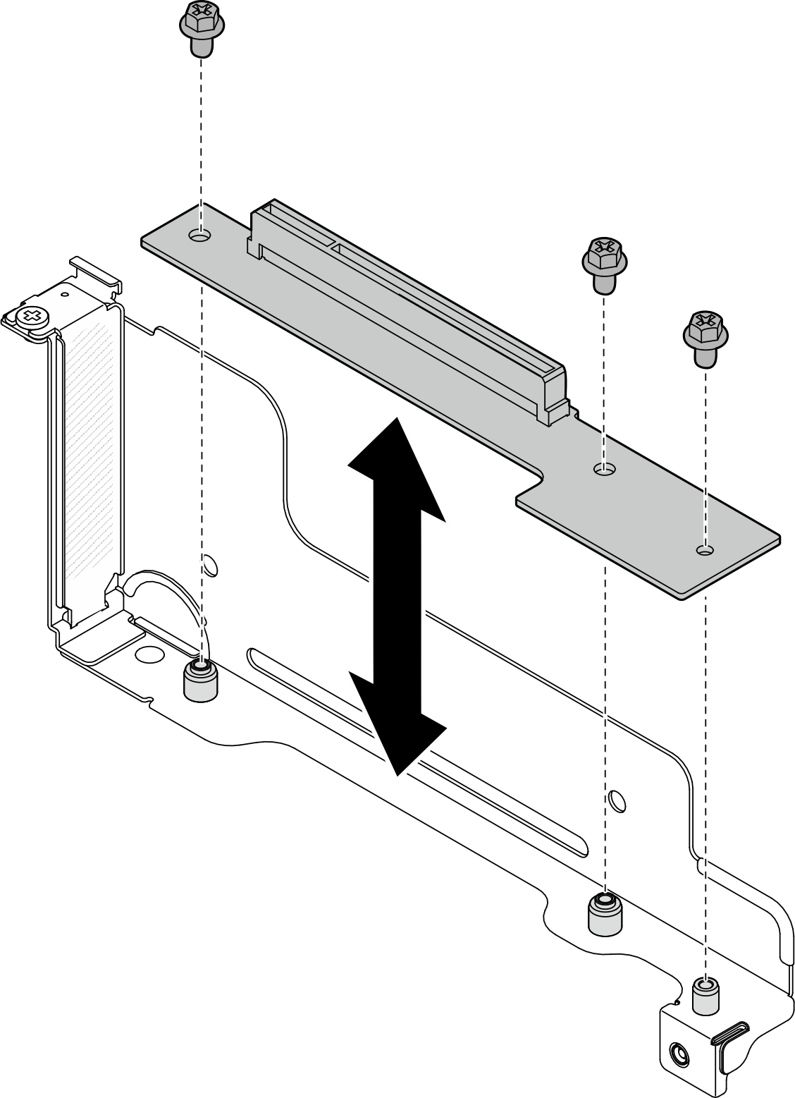
- Install the PCIe riser assembly to the node.
 Connect the PCIe riser power cable to the riser.
 Align the edges of the PCIe riser assembly with the edges of the node; then, place the PCIe riser assembly into place until it is securely seated.
 Tighten the captive screw to secure the PCIe riser assembly to the node.
Figure 2. Installation of the PCIe riser assembly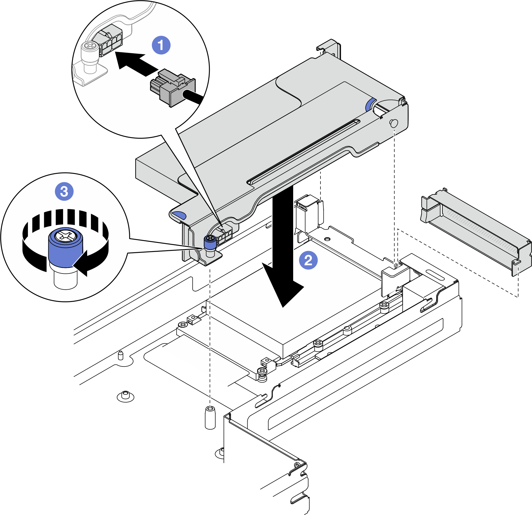
After you finish
- If necessary, reinstall the GPU air duct (see Install a GPU air duct).
- Make sure that all the required cables are routed and connected correctly; then, reinstall the top cover (see Install the top cover).
- Reinstall the node into the chassis (see Install a node to the chassis).
- Make sure that the required power supply units are installed and power cords are connected; then, power on the node (see Install a hot-swap power supply and Power on the node).
- Proceed to complete the parts replacement (see Complete the parts replacement).
Demo video
Give documentation feedback