Install the shared PCIe dual adapters
Use this information to install the shared PCIe dual adapters.
- Read the following section(s) to ensure that you work safely.
Power off all the compute nodes and peripheral devices (see Power off the compute node).
Disengage all the compute nodes from the enclosure.
Disconnect the power cords and all external cables from the rear of the enclosure.
If the cable management arm is installed, remove it (see Remove the cable management arm).
Remove the shuttle from the enclosure (see Remove the shuttle).
Locate the PCIe slots to install the adapters into.
Figure 1. Location of shared PCIe dual adaptersTable 1. Location of shared PCIe dual adapters from the rear Primary adapter
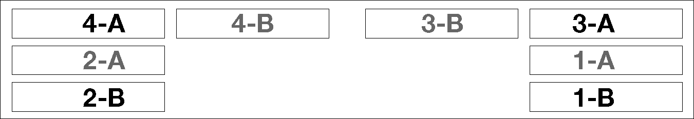
Auxiliary adapter
- - - - Auxiliary adapter
Primary adapter
Note- To ensure sufficient space for the cable:
Before installing the adapters into PCIe slot 3-A and 1-B, make sure slot 1-A is empty.
Before installing the adapters into PCIe slot 4-A and 2-B, make sure slot 2-A is empty.
When one or more pairs of shared PCIe dual adapters are installed in the shuttle, make sure slot 3-B and 4-B are both empty.
Touch the static-protective package that contains the adapter to any unpainted metal surface on the solution; then, remove the adapter from the package.
Install the shared PCIe dual adapters into PCIe slot 3-A and 1-B
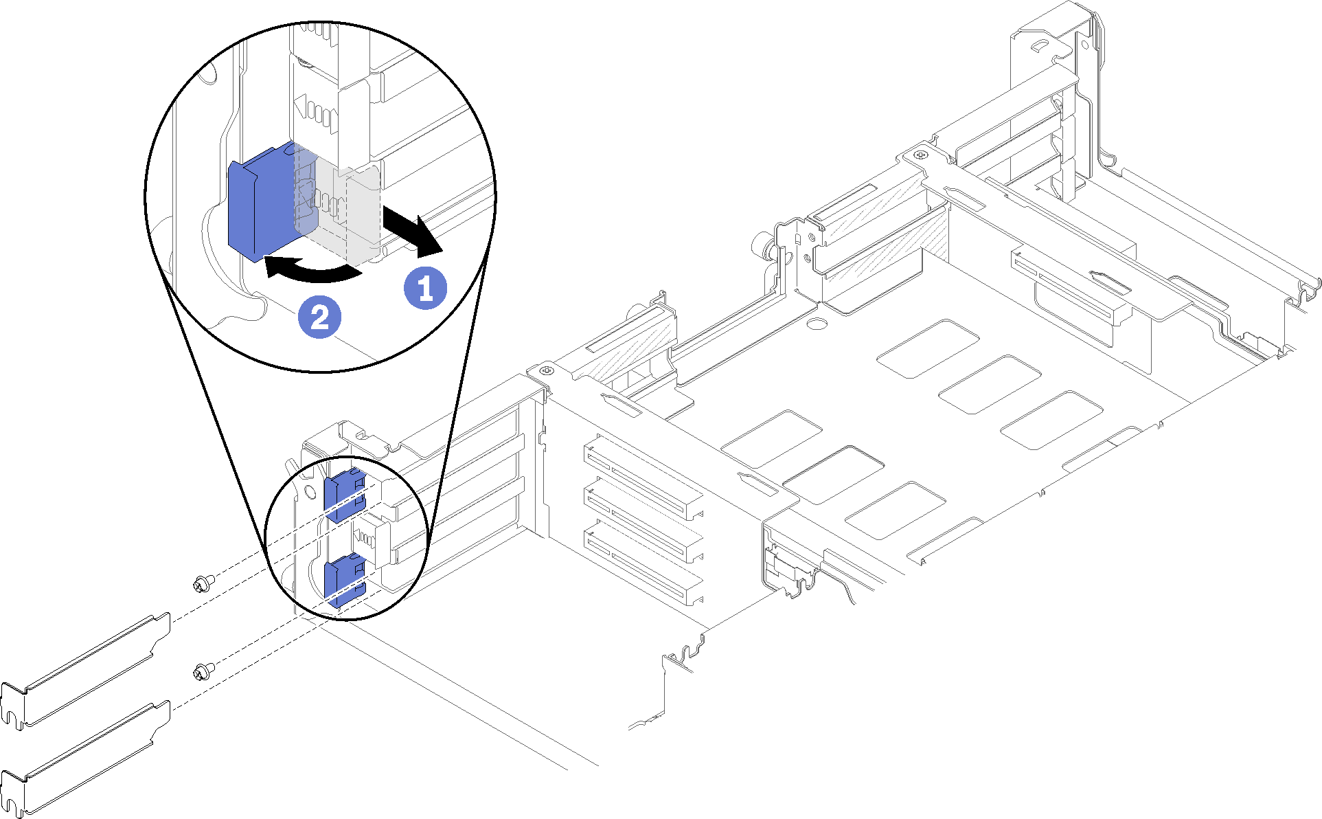
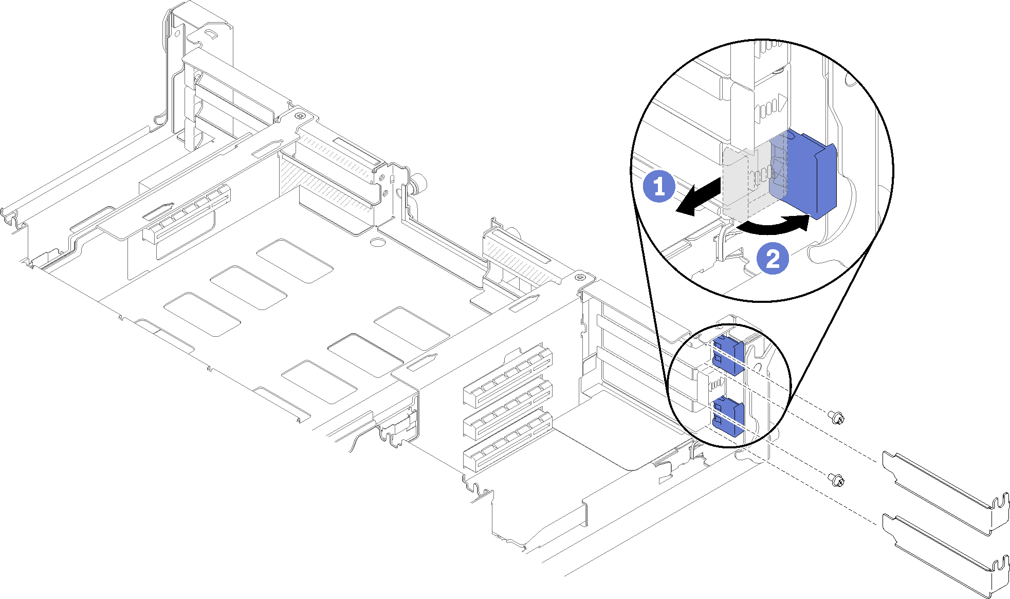
- Figure 2. Removing expansion-slot covers and screws
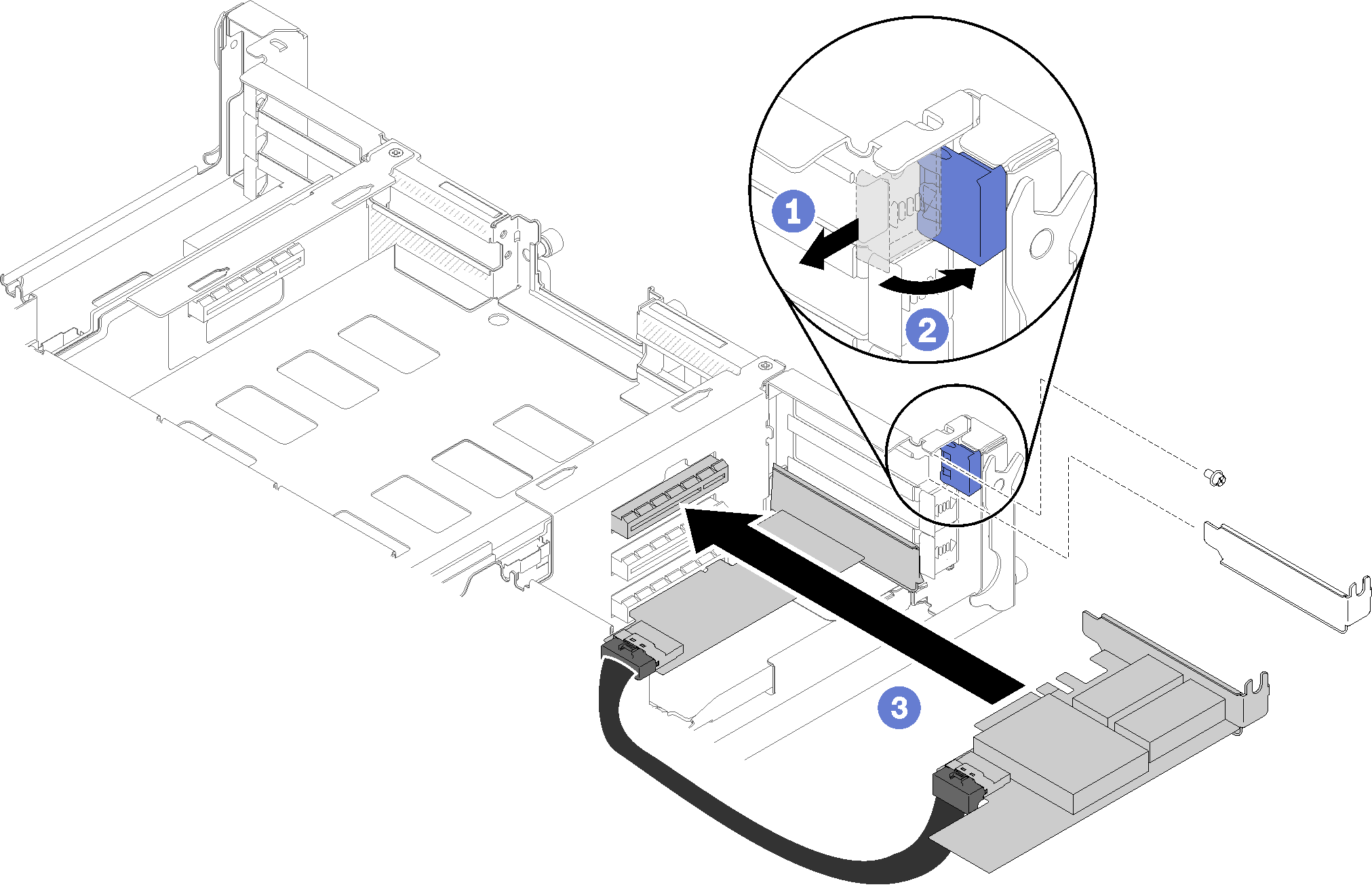
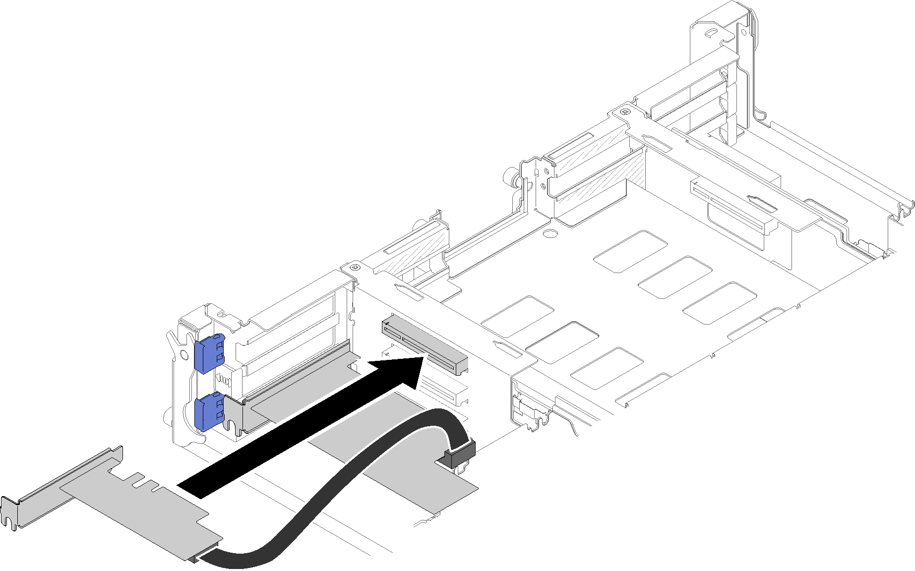
- Align the primary adapter with the bottom slot connector , and firmly press it in.Figure 3. Installing the primary adapter
- Align the auxiliary adapter with the top slot connector, and firmly press it in.Figure 4. Installing the auxiliary adapter
Install the shared PCIe dual adapters into PCIe slot 4-A and 2-B
- If expansion-slot covers and screws are installed in these slots, remove them.Figure 5. Removing expansion-slot covers and screws
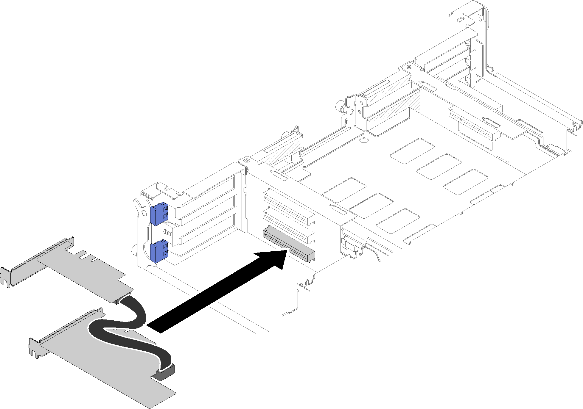
- Align the auxiliary adapter with the bottom slot connector, and firmly press it in.Figure 6. Installing the auxiliary adapter
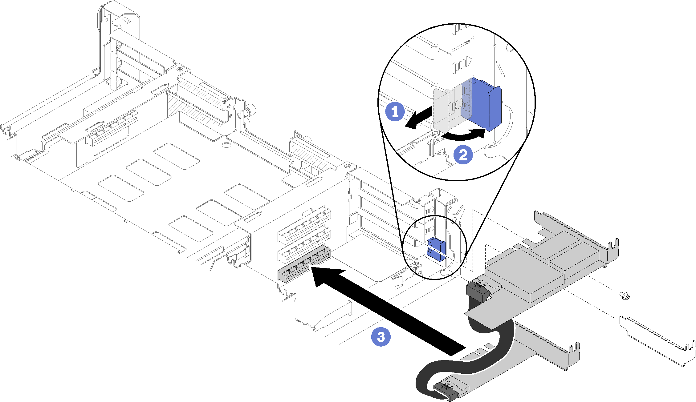
- Align the primary adapter with the top slot connector, and firmly press it in.Figure 7. Installing the primary adapter