Install a compute node in the enclosure
Use this procedure to install a compute node in the D2 Enclosure.
- Read the following section(s) to ensure that you work safely.
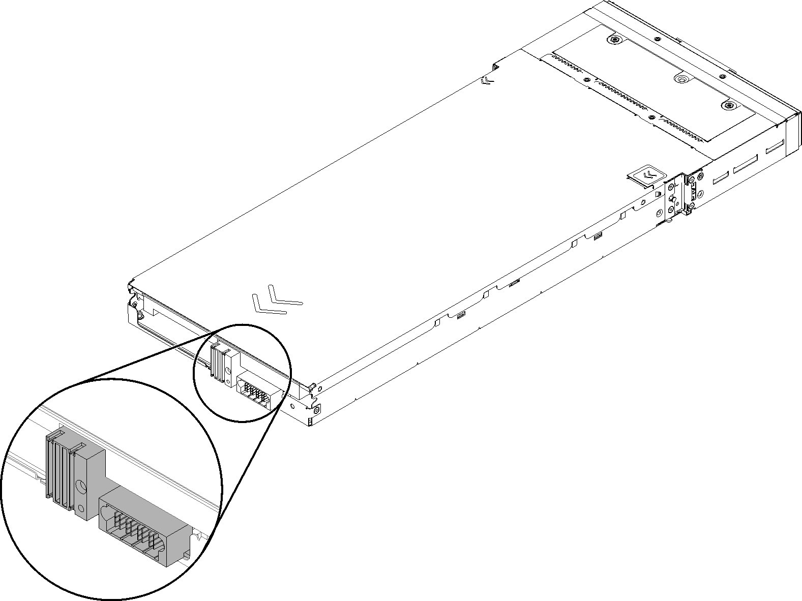
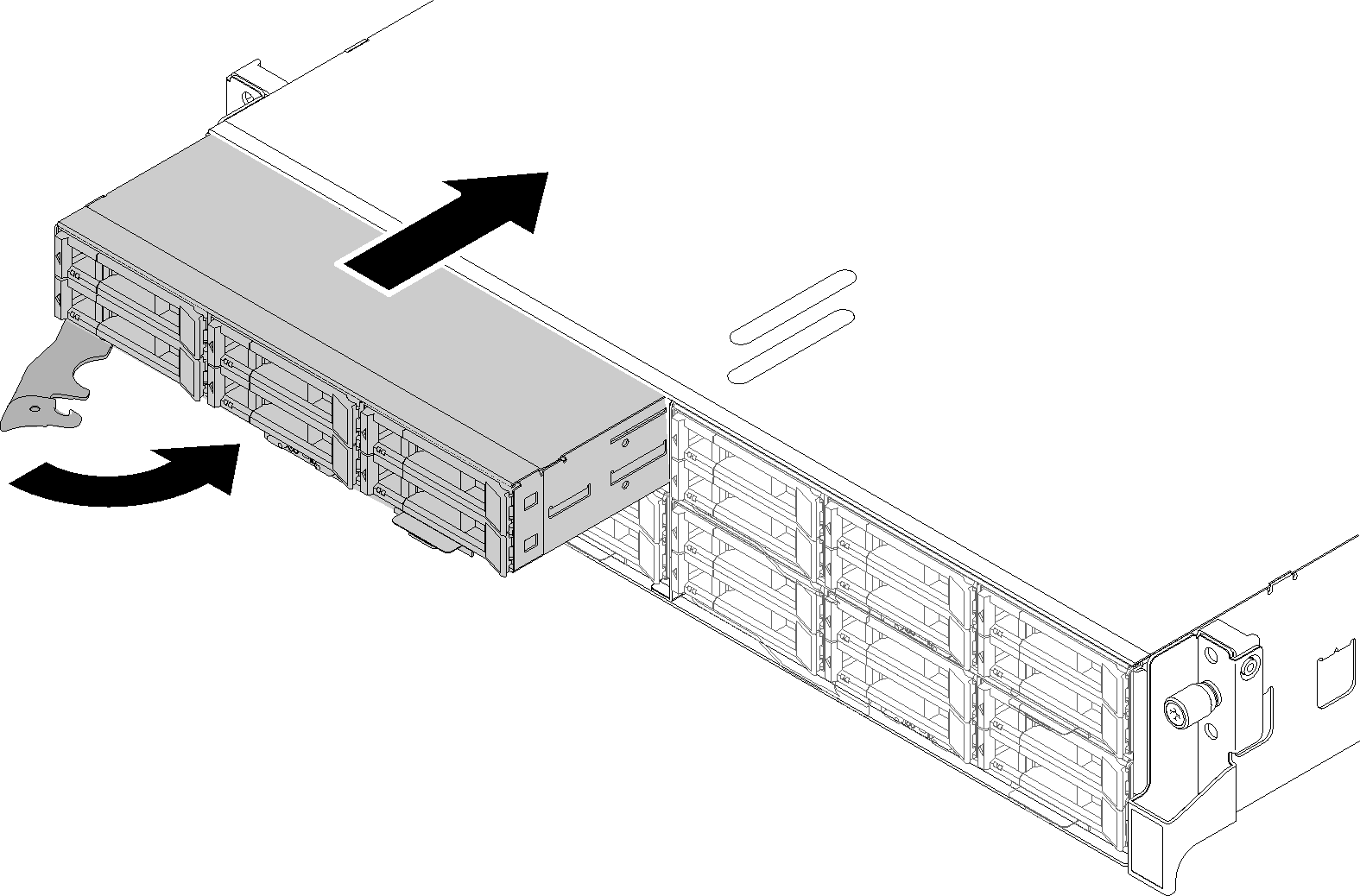
Complete the following steps to install the compute node in a enclosure.
Check the power LED to make sure it transitions between fast blink and slow blink to indicate the node is ready to be powered on; then, power on the node.
Make sure that the power LED on the compute node control panel is lit continuously, indicating that the compute node is receiving power and is turned on.
If you have other compute nodes to install, do so now.
If this is the initial installation of the node in the enclosure, you must configure the node through the Lenovo XClarity Provisioning Manager and install the node operating system. See OS Installation with Lenovo XClarity Provisioning Manager for more details.
If compute node access over local console is not available:
Access Lenovo XClarity Controller web interface (see Accessing the XClarity Controller web interface).
Set up Lenovo XClarity Controller network connection through Lenovo XClarity Provisioning Manager (see Setting up the XClarity Controller network connection through the XClarity Provisioning Manager).
Log in to Lenovo XClarity Controller (see Logging in to the XClarity Controller).
If you have changed the configuration of the compute node or if you are installing a different compute node from the one that you removed, you must configure the compute node through the Setup utility, and you might have to install the compute node operating system, see System configuration for more details.
If you are installing a different compute node from the one that you removed, update the machine type and serial number with new vital product data (VPD). Use the Lenovo XClarity Provisioning Manager to update the machine type and serial number. See Update the machine type and serial number.
You can place identifying information on the pull out label tab that are accessible from the front of the node.
Demo video