Install the KVM breakout module
Use this information to install the KVM breakout module.
- Read the following section(s) to ensure that you work safely.
Turn off the corresponding compute node that you are going to perform the task on.
Remove the node (see Remove a compute node from the enclosure).
Remove the compute node cover (see Remove the compute node cover).
Remove the air baffle (see Remove the air baffle).
Complete the following steps to install the KVM breakout module.
- Carefully route cables through the drive bay and the drive backplane.
The right KVM breakout module (for four 2.5-inch-drive model)
Figure 1. Right KVM breakout module installation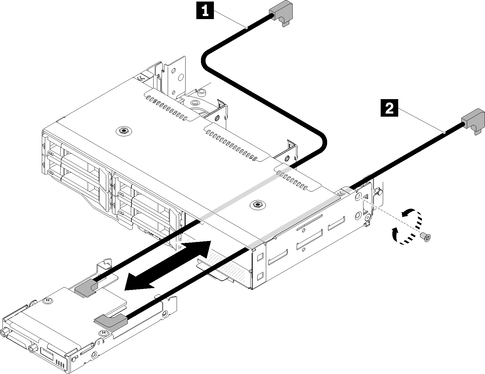
Table 1. Components on the right KVM breakout module installation 1 Long signal cable 2 Short signal cable AttentionMake sure the USB 3.0 connector is on your right side as illustrated to ensure the correct installation.Figure 2. KVM breakout module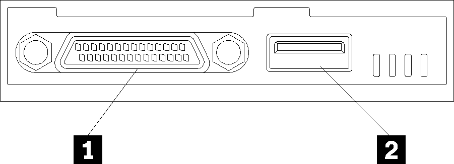
Table 2. KVM breakout module 1 KVM connector 2 USB 3.0 connector
The left KVM breakout module (for six 2.5-inch-drive model)
Figure 3. Left KVM breakout module installation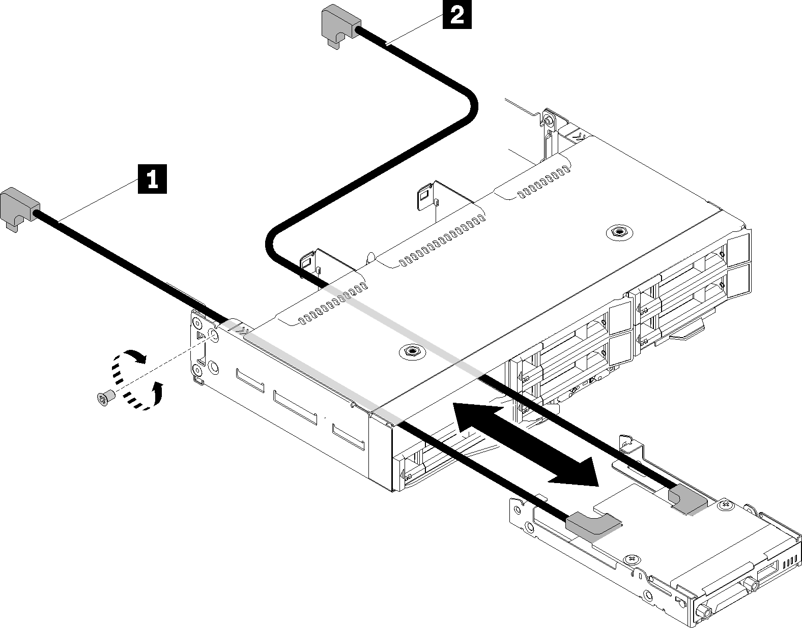
Table 3. Components on the left KVM breakout module installation 1 Short signal cable 2 Long signal cable AttentionMake sure the USB 3.0 connector is on your right side as illustrated to ensure the correct installation.Figure 4. KVM breakout moduleTable 4. KVM breakout module 1 KVM connector 2 USB 3.0 connector
- Connect required cables to connectors as shown in the following illustrations.NoteManage cables in plastic cable guides located on side of compute node.
The right KVM breakout module (for four 2.5-inch-drive model)
Figure 5. Right KVM breakout module cable routing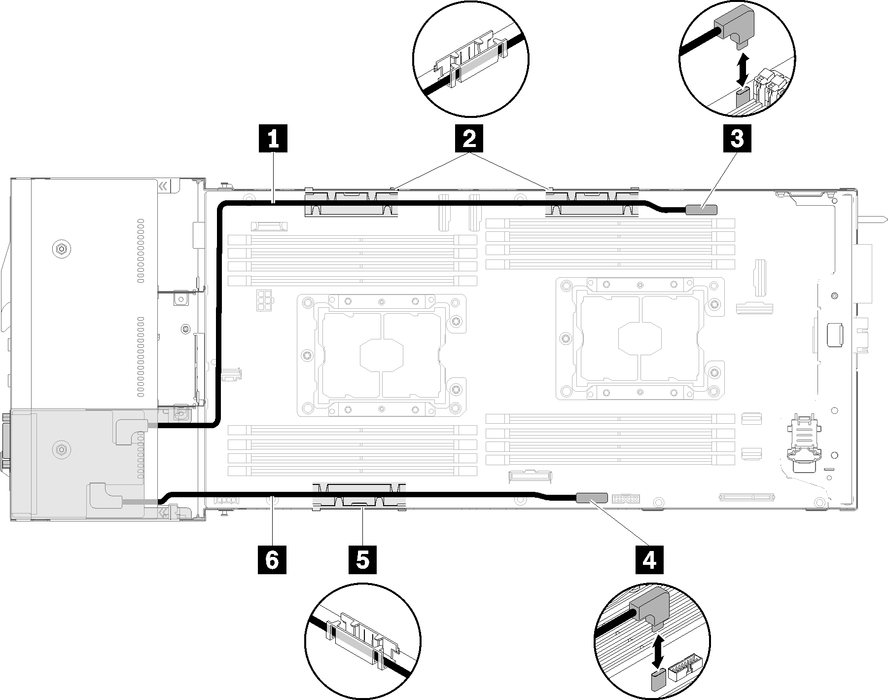
Table 5. Components on the right KVM breakout module cable routing 1 Long signal cable 3 KVM breakout cable connector 2 5 Internal cable management basket 4 USB connector 6 Short signal cable
The left KVM breakout module (for six 2.5-inch-drive model)
Figure 6. Left KVM breakout module cable routing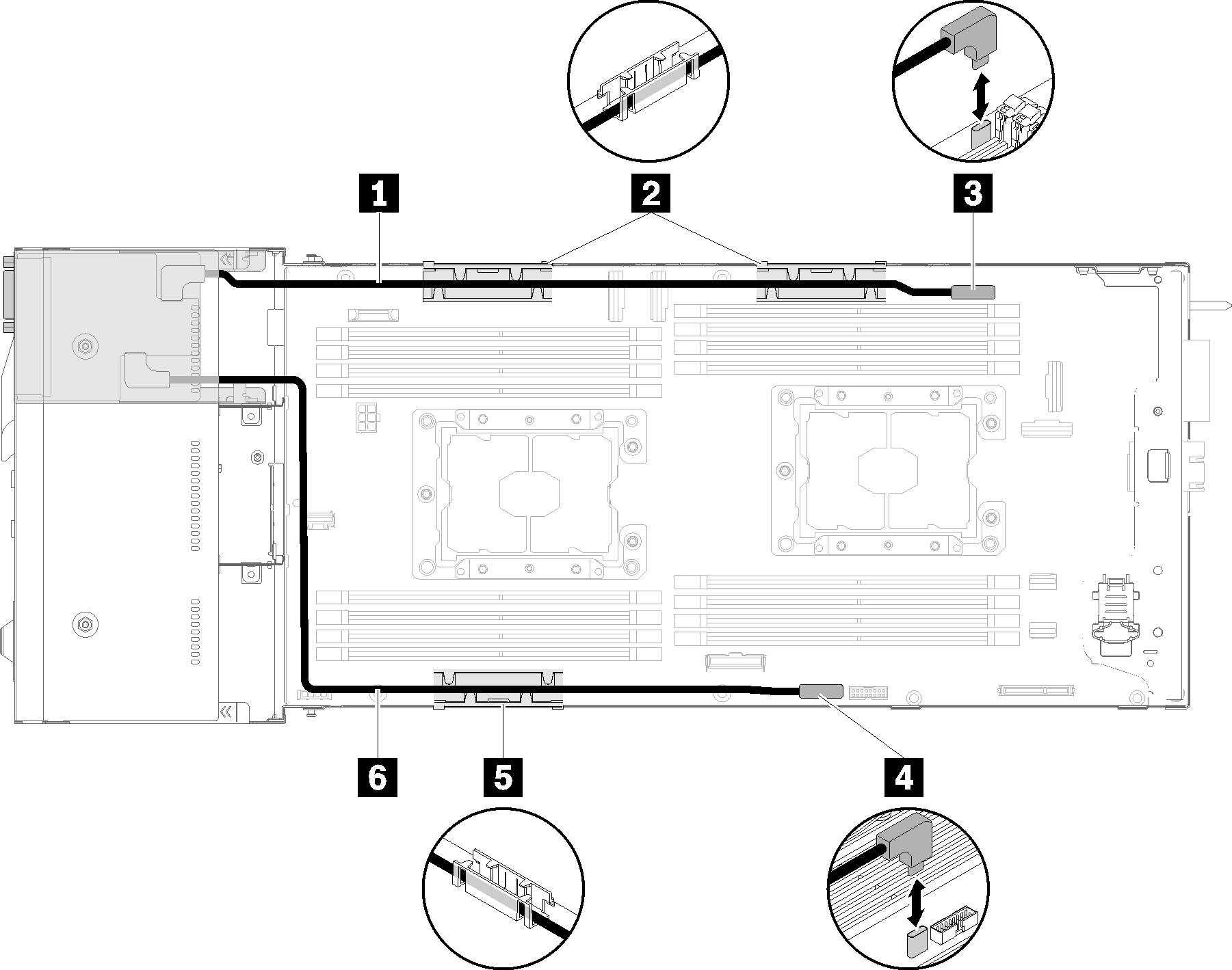
Table 6. Components on the left KVM breakout module cable routing 1 Short signal cable 3 KVM breakout cable connector 2 5 Internal cable management basket 4 USB connector 6 Long signal cable
NoteWhile KVM breakout cable is connected, the USB key should not be wider than 19 mm.
Reinstall the air baffle (see Install the air baffle).
Reinstall the node cover (see Install the compute node cover).
Reinstall the compute node (see Install a compute node in the enclosure).
Reconnect the power cords and any cables that you removed.
Check the power LED to make sure it transitions between fast blink and slow blink to indicate the node is ready to be powered on.
Demo video