Install a processor-heat-sink module
The processor and heat sink are removed together as part of a processor-heat-sink-module (PHM) assembly. PHM installation requires a Torx T30 driver.


Each processor socket must always contain a cover or a PHM. When removing or installing a PHM, protect empty processor sockets with a cover.
Do not touch the processor socket or processor contacts. Processor-socket contacts are very fragile and easily damaged. Contaminants on the processor contacts, such as oil from your skin, can cause connection failures.
Remove and install only one PHM at a time. If the system board supports multiple processors, install the PHMs starting with the first processor socket.
Do not allow the thermal grease on the processor or heat sink to come in contact with anything. Contact with any surface can compromise the thermal grease, rendering it ineffective. Thermal grease can damage components, such as electrical connectors in the processor socket. Do not remove the grease cover from a heat sink until you are instructed to do so.
- Thermal grease can stay functional on the heat sink for two years. When installing a new heat sink, make sure to check the manufacturing date to ensure the thermal grease is still functioning. If the date is over two years ago, replace the thermal grease to avoid seating issues.
PHMs are keyed for the socket where they can be installed and for their orientation in the socket.
See Lenovo ServerProven website for a list of processors supported for your system. All processors on the system board must have the same speed, number of cores, and frequency.
Before you install a new PHM or replacement processor, update your system firmware to the latest level. See Update the firmware.
Installing an additional PHM can change the memory requirements for your system. See Install a memory module for a list of processor-to-memory relationships.
Optional devices available for your system might have specific processor requirements. See the documentation that comes with the optional device for information.
Figure 1. Processor locations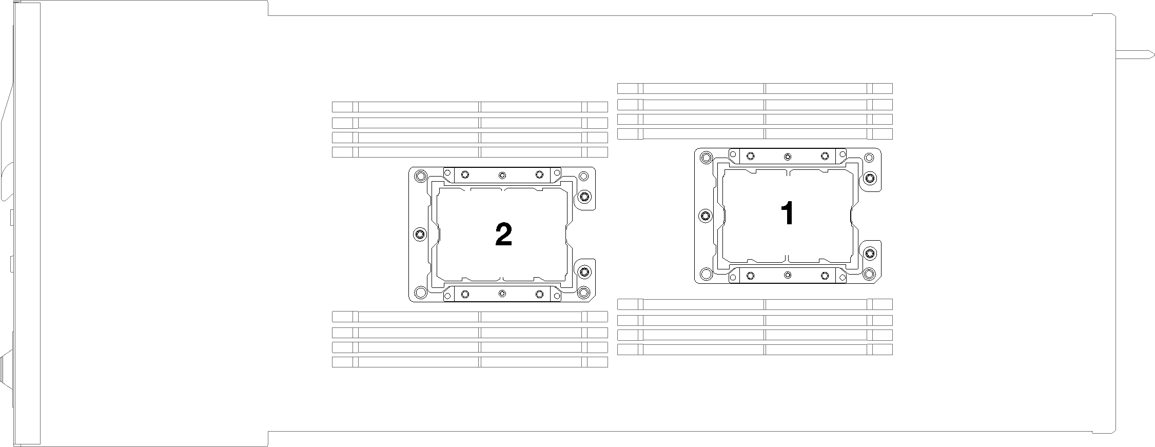
The following types of heat sinks are applicable to SD530:
Low voltage configuration
108x108x24.5mm heat sink is only applicable to processor socket 1.
85x108x24.5mm heat sink is only applicable to processor socket 2.
High voltage configuration
T-shaped heat sink is only applicable to processor socket 1.
105x108x24.5mm heat sink is only applicable to processor socket 2.
- Read the following section(s) to ensure that you work safely.
Turn off the corresponding compute node that you are going to perform the task on.
- Remove the compute node (see Remove a compute node from the enclosure).
- Remove the compute node cover (see Remove the compute node cover).
- Remove the air baffle (see Remove the air baffle).
- If the processor comes with a T-shaped hear sink, secure the heat sink with two screws on the sides of the node.Figure 2. Securing the T-shaped heat sink with two screws
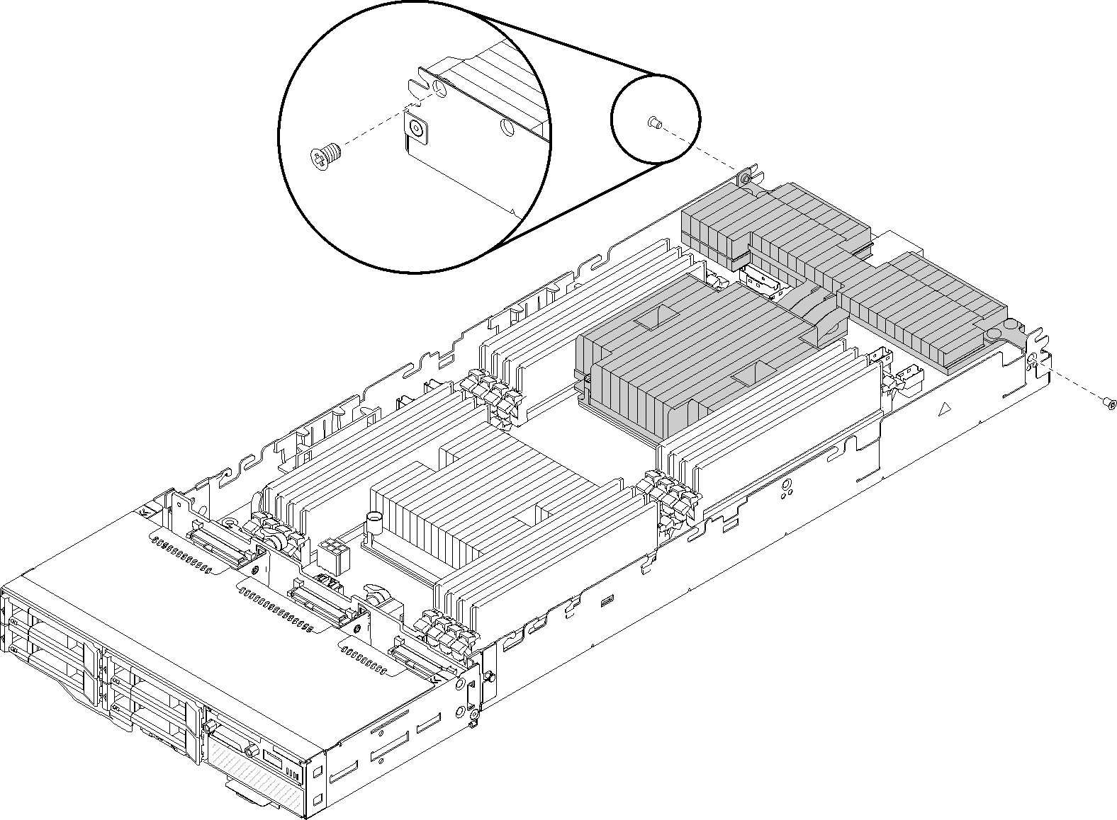 NoteUse Phillips #1 driver on these two screws.
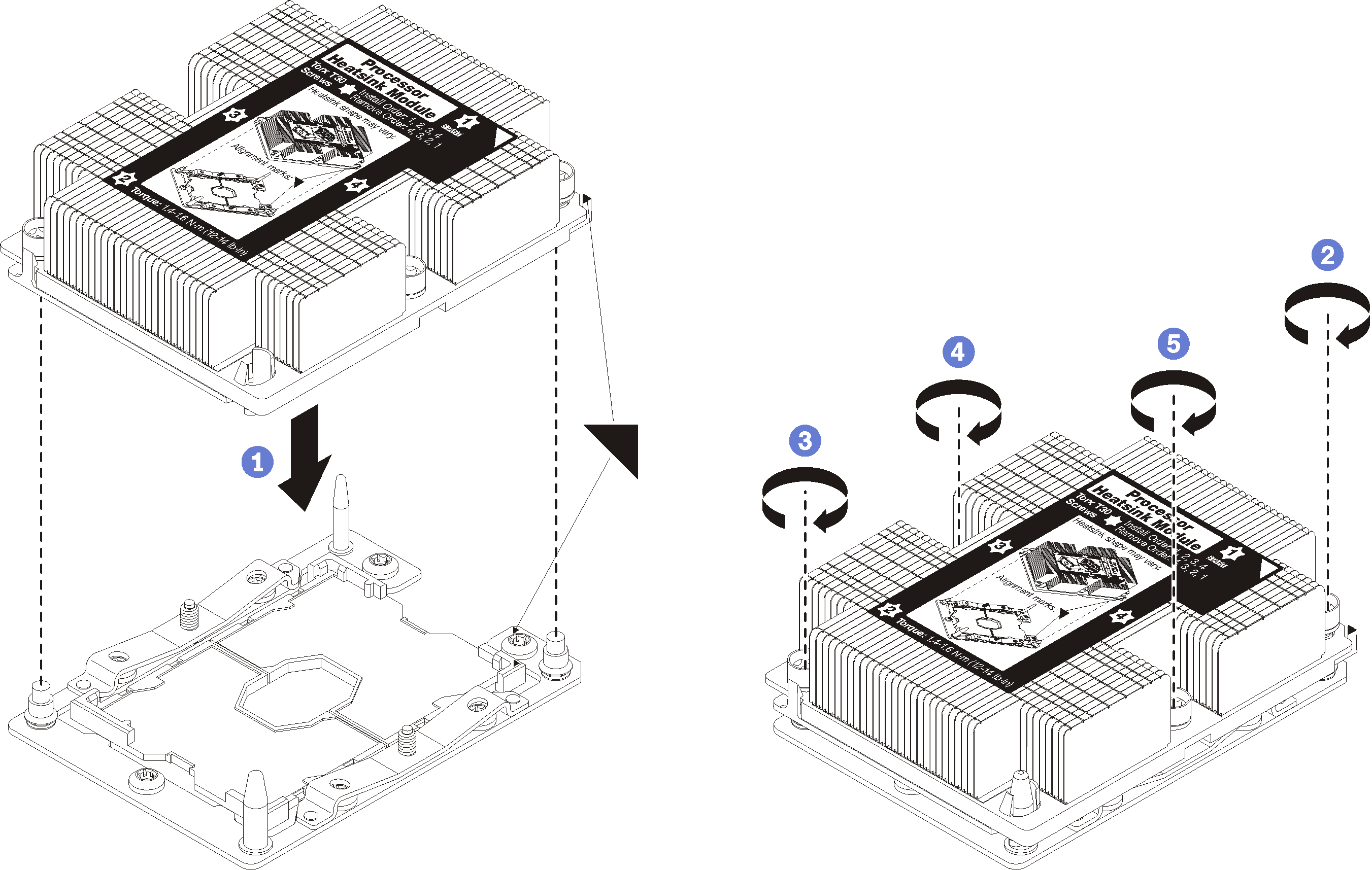
 - Install the processor-heat-sink module on the system board.Figure 3. Installing a PHM
If there are memory modules to install, install them. See Install a memory module.
Reinstall the air baffle (see Install the air baffle).
Reinstall the compute node cover (see Install the compute node cover).
Reinstall the compute node (see Install a compute node in the enclosure).
Check the power LED to make sure it transitions between fast blink and slow blink to indicate the node is ready to be powered on.