Install a power bus bar
Follow instructions in this section to install a power bus bar.
About this task
To avoid potential danger, make sure to read and follow the safety information.
Attention
Read Installation Guidelines and Safety inspection checklist to make sure that you work safely.
Touch the static-protective package that contains the component to any unpainted metal surface on the node and chassis; then, take the component out of the package and place it on a static-protective surface.
Note
For reference, the torque required for the screws to be fully tightened to the power bus bar is 12 +/- 0.5 lbf-in.
Procedure
- Install the power bus bar to the node.
 Align the screw holes on the power bus bar with the corresponding screw holes on the system board and power distribution board; then, lower the power bus bar into place.
 Tighten the main system board screw to secure the power bus bar to the system board.
 Tighten the main PDB screw to secure the power bus bar to the power distribution board.Figure 1. Installation of the power bus bar
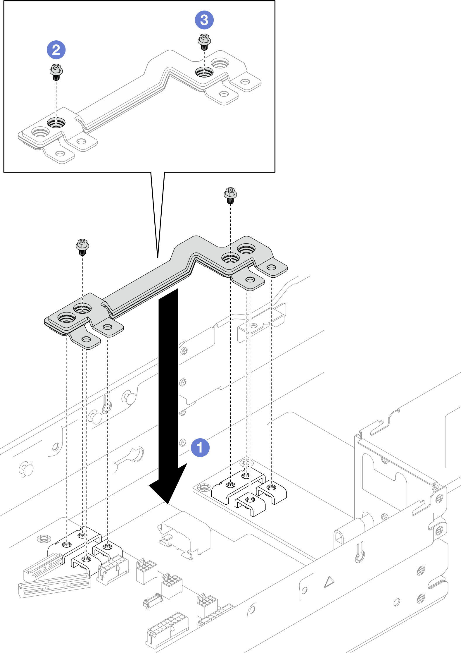
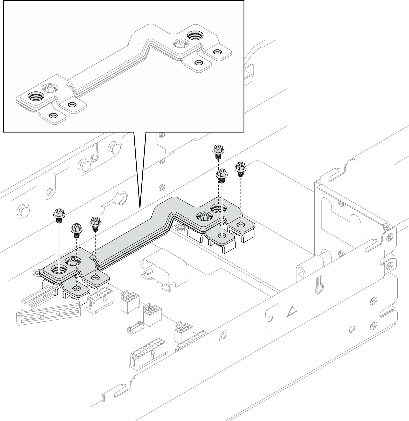
- Tighten the six outer screws to secure the power bus bar.Figure 2. Installation of the power bus bar outer screws
After you finish
- If necessary, reinstall the PCIe riser assembly to the node and reconnect the required PCIe cables to the system board (see Install a PCIe riser assembly and PCIe riser cable routing).
- Reinstall the fan cage to the node and reconnect all the fan cables to the system board (see Install a fan cage).
- If necessary, reinstall the GPU air duct (see Install a GPU air duct).
- If necessary, reinstall the internal adapter bracket and reconnect all the required cables to the internal adapter (see Install an internal adapter bracket and 2.5-inch drive backplane cable routing ).
- Make sure that all the required cables are routed and connected correctly; then, reinstall the top cover (see Install the top cover).
- Reinstall the node into the chassis (see Install a node to the chassis).
- Make sure that the required power supply units are installed and power cords are connected; then, power on the node (see Install a hot-swap power supply and Power on the node).
- Proceed to complete the parts replacement (see Complete the parts replacement).
Demo video
Give documentation feedback