Remove the processor and heat sink
This task has instructions for removing the assembled processor and heat sink, known as a processor-heat-sink module (PHM). This task requires a Torx T30 driver. This procedure must be executed by a trained technician.
About this task
To avoid potential danger, make sure to read and follow the safety information.
Read Installation Guidelines and Safety inspection checklist to make sure that you work safely.
To transfer Intel® On Demand Suite from the defective processor to the new processor, read the PPIN of the defective processor before powering off the system. For more information, see Enable Intel® On Demand.
- Each processor socket must always contain a cover or a PHM. When removing or installing a PHM, protect the empty processor sockets with a cover.
- Do not touch the processor socket or processor contacts. Processor-socket contacts are very fragile and easily damaged. Contaminants on the processor contacts, such as oil from your skin, can cause connection failures.
- Do not allow the thermal grease on the processor or heat sink to come in contact with anything. Contact with any surface can compromise the thermal grease, rendering it ineffective. Thermal grease can damage components, such as the electrical connectors in the processor socket.
- Remove and install only one PHM at a time. If the system supports multiple processors, install the PHMs starting with the first processor socket.
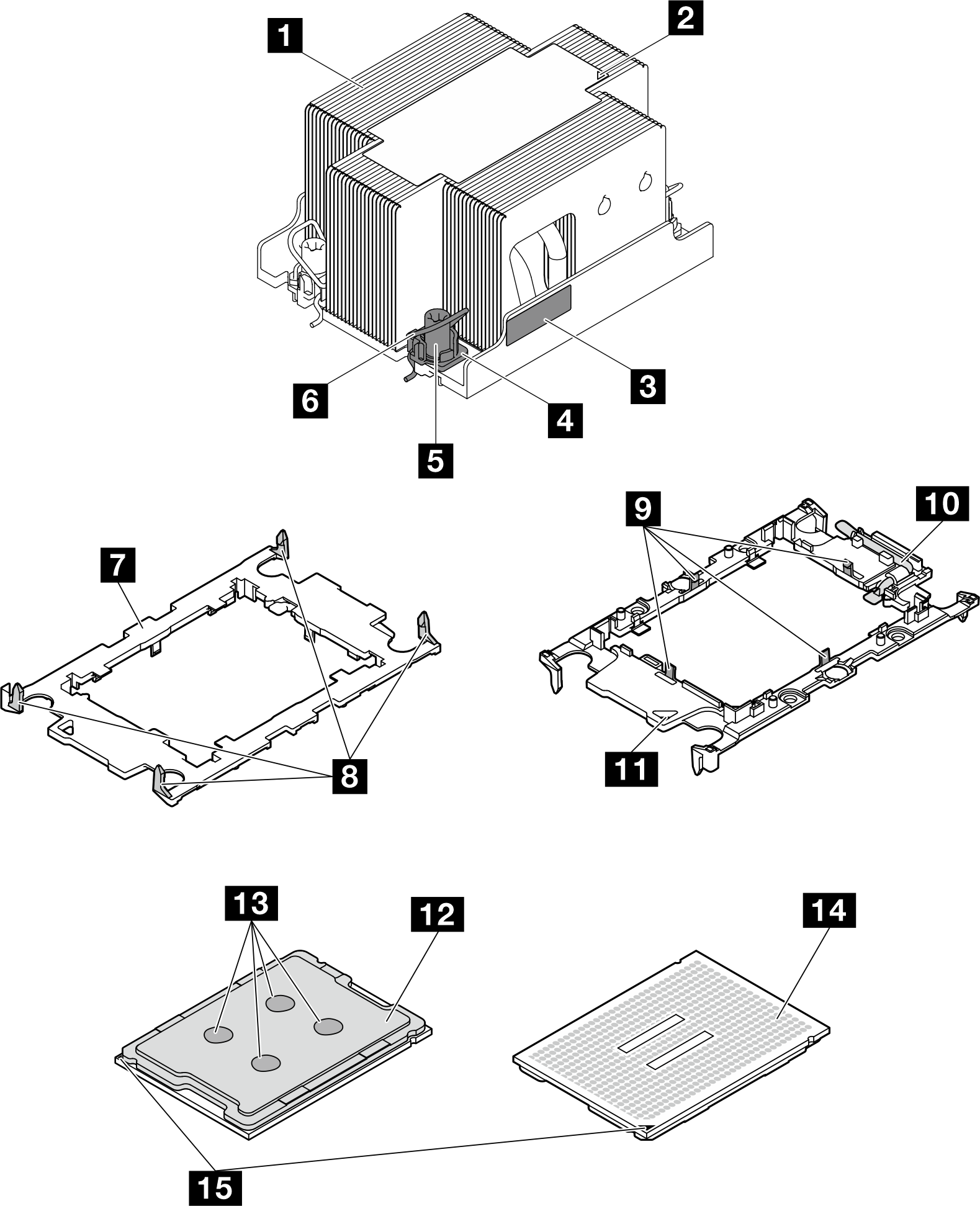
| 1 Heat sink | 9 Clips to secure processor in carrier |
| 2 Heat sink triangular mark | 10 Processor ejector handle |
| 3 Processor identification label | 11 Carrier triangular mark |
| 4 Nut and wire bail retainer | 12 Processor heat spreader |
| 5 Torx T30 nut | 13 Thermal grease |
| 6 Anti-tilt wire bail | 14 Processor contacts |
| 7 Processor carrier | 15 Processor triangular mark |
| 8 Clips to secure carrier to heat sink |
Procedure
- Make preparations for this task.
- Power off the node (see Power off the node); then, disconnect all external cables from the node.NoteIf necessary, press the release clip with a flat-head screwdriver to remove an external network cable from the rear of a 2U node.

- Power off the node (see Power off the node); then, disconnect all external cables from the node.
- Remove the PHM from the system board.Important
- Do not touch the contacts on the processor contacts. Contaminants on the processor contacts, such as oil from your skin, can cause connection failures.
- Keep the processor socket clean from any object to prevent possible damages.
- Do not allow the thermal grease on the processor or heat sink to come in contact with anything. Contact with any surface can compromise the thermal grease, rendering it ineffective. Thermal grease can damage components, such as the electrical connectors in the processor socket.
 Fully loosen the Torx T30 nuts on the PHM in the removal sequence shown on the heat-sink label.Important
- For reference, the torque required for the screws to be fully tightened/removed is 10+/- 2.0 lbf-in, 1.1+/- 0.2 N-m.
- To prevent damage to components, make sure to follow the indicated tightening/loosening sequence.
 Rotate the anti-tilt wire bails inward.
 Carefully lift the PHM from the processor socket. If the PHM cannot be fully lifted out of the socket, further loosen the Torx T30 nuts and try lifting the PHM again.Figure 2. Removal of the 2U Standard PHM
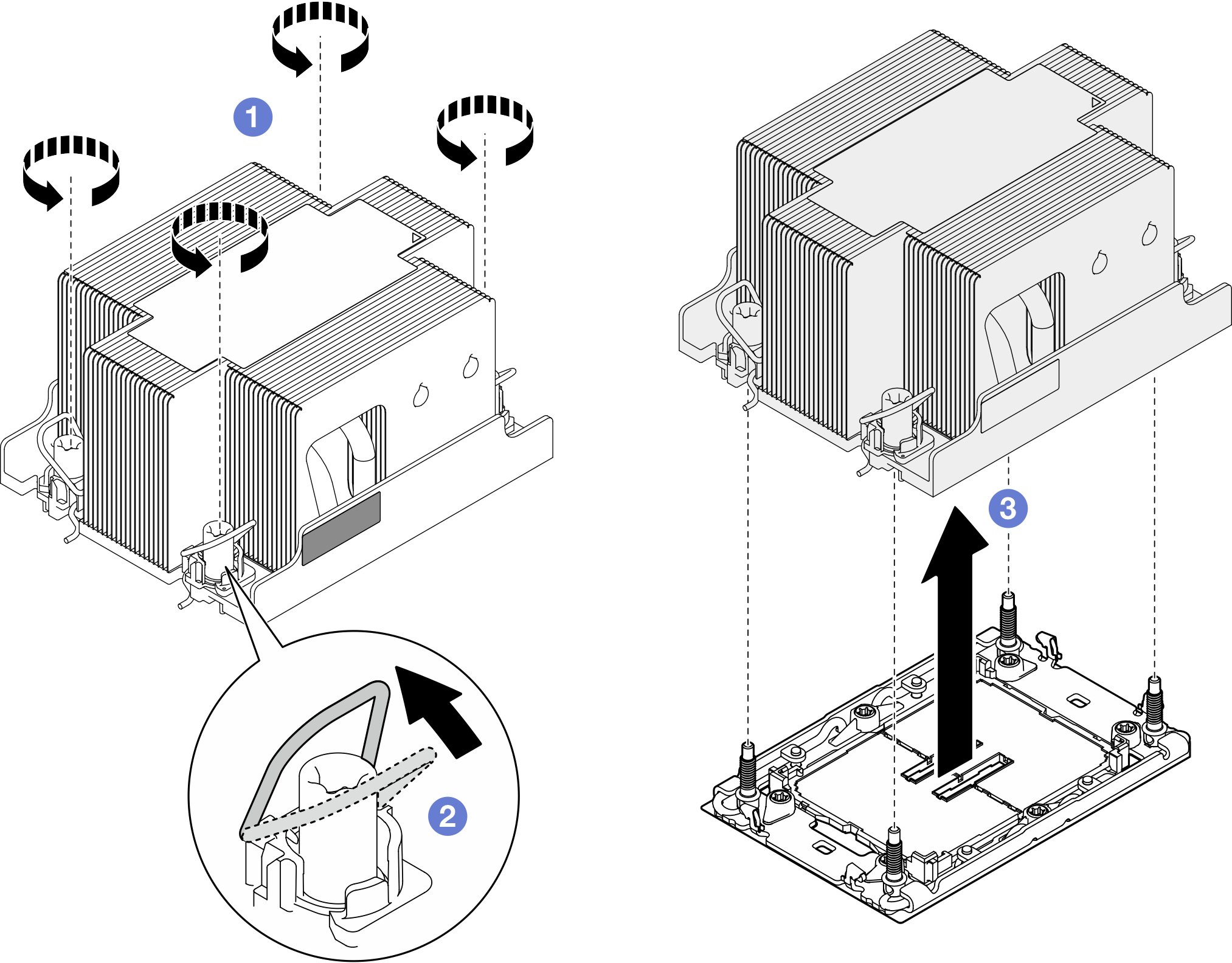 Figure 3. 2U performance PHM removal
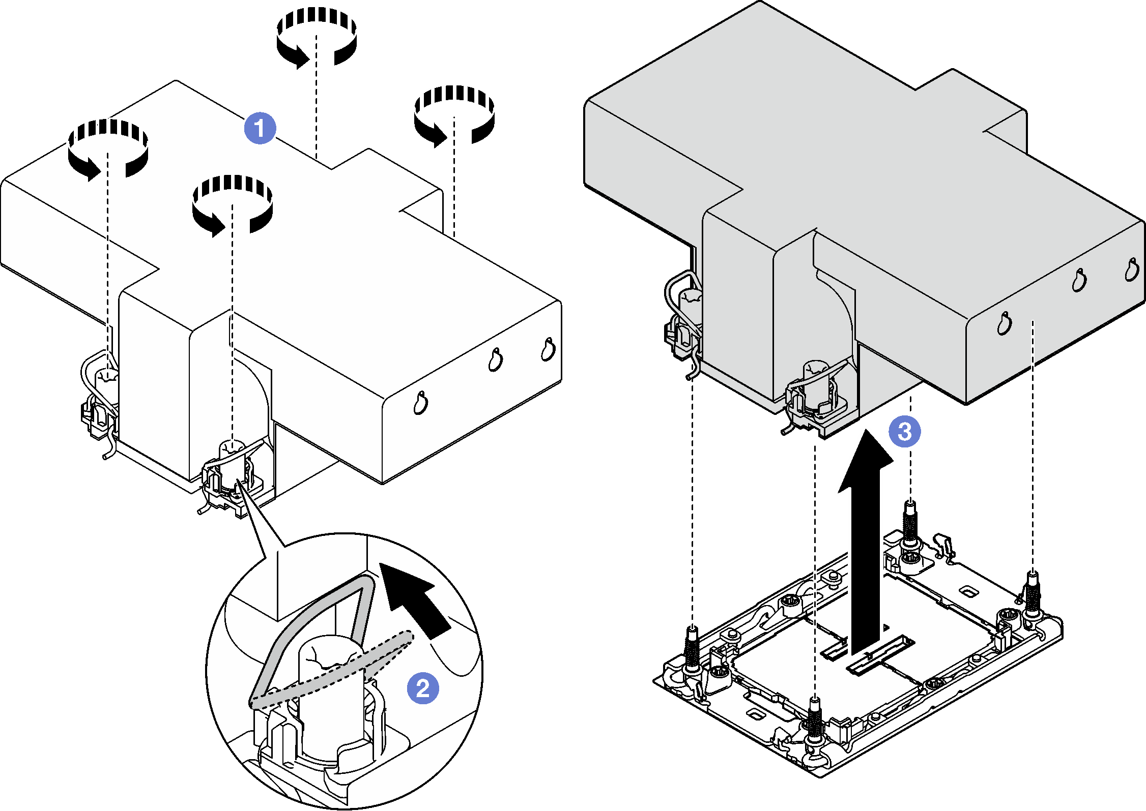
After you finish
- Each processor socket must always contain a cover or a PHM. Protect an empty processor socket with a cover or install a new PHM.
- If you are removing the PHM as part of a system board replacement, set the PHM aside.
- If you are reusing the processor or heat sink, separate the processor from its retainer. See Separate the processor from carrier and heat sink.
- Install a replacement unit (see Install a processor and heat sink).
- If you are instructed to return the component or optional device, follow all packaging instructions, and use any packaging materials for shipping that are supplied to you.
To transfer Intel® On Demand Suite from the defective processor to the new processor, see Enable Intel® On Demand.
Demo video