Install the OSFP module
Use this information to install the OSFP module.
About this task
Required tools
Make sure that you have the SD650-N V3 OSFP Putty Pad Kit to properly replace the component.
| Screw Type/Usage | Screwdriver Type |
|---|---|
| Hex screw | 4.5 mm hex head screwdriver |
To identify the gap pad/putty pad location and orientation, see Gap pad/Putty pad identification and location.
Before replacing the gap pad/putty pad, gently clean the interface plate or the hardware surface with an alcohol cleaning pad.
Hold the gap pad/putty pad carefully to avoid deformation. Make sure no screw hole or opening is blocked by the gap pad/putty pad material.
Do not use expired putty pad. Check the expiry date on putty pad package. If the putty pads are expired, acquire new ones to properly replace them.
Read Installation Guidelines and Safety inspection checklist to ensure that you work safely.
Turn off the corresponding DWC tray that you are going to perform the task on.
Go to Drivers and Software download website for ThinkSystem SD650-N V3 to see the latest firmware and driver updates for your server.
Go to Update the firmware for more information on firmware updating tools.
- A video of this procedure is available at YouTube.
Procedure
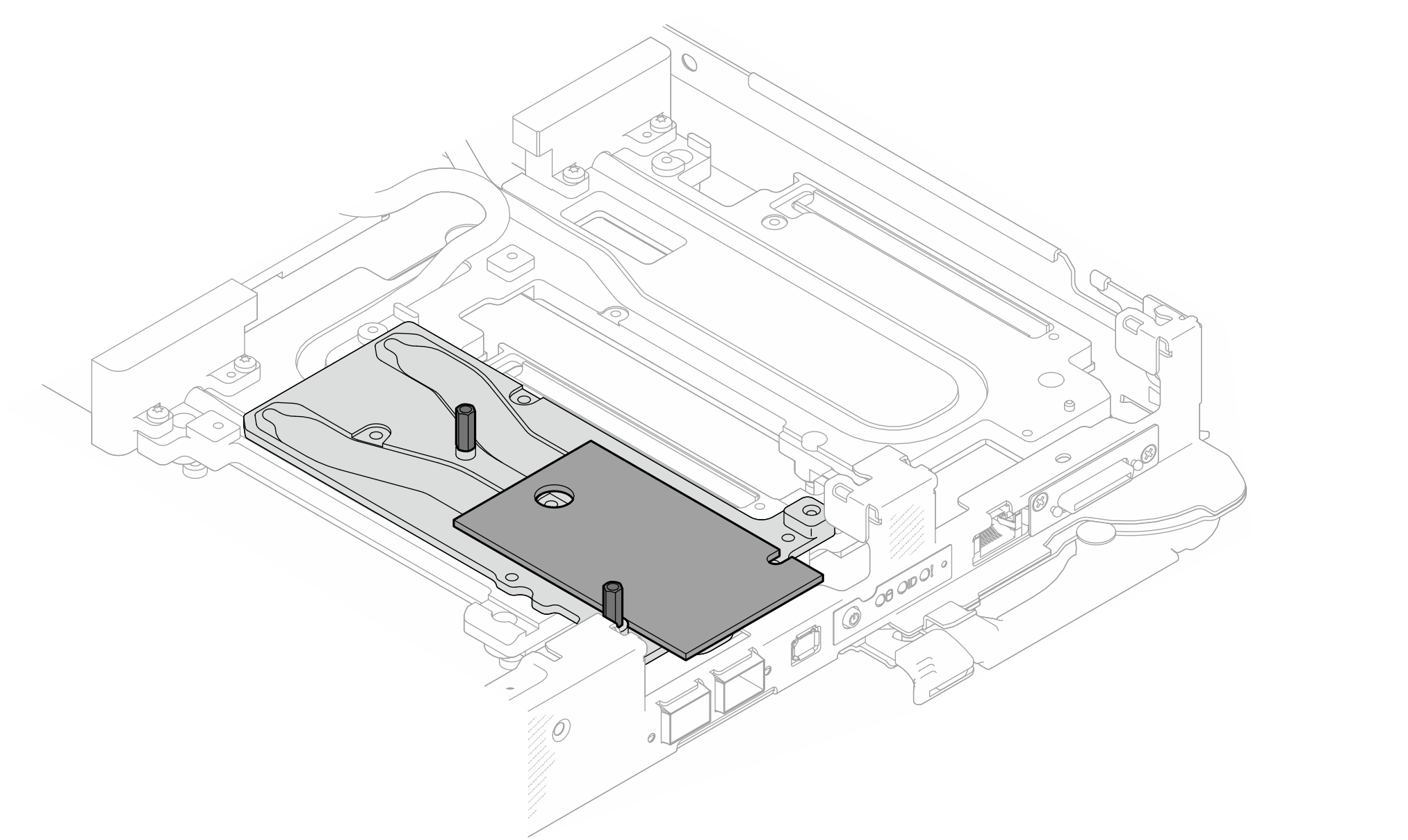
- Replace the putty pad on the OSFP module conduction plate with a new one. Make sure to follow Gap pad/putty pad replacement guidelines.Figure 1. Replacing the putty pad on the OSFP module
- Connect the two OSFP module power cables. Connect power cable labeled as P1 to Power connector 1 on the OSFP module, and P2 to Power connector 2.
OSFP module connects to Power cable 1 Power connector 1 2 P1 4 Power connector 2 4 P2 Figure 2. OSFP module power cables installation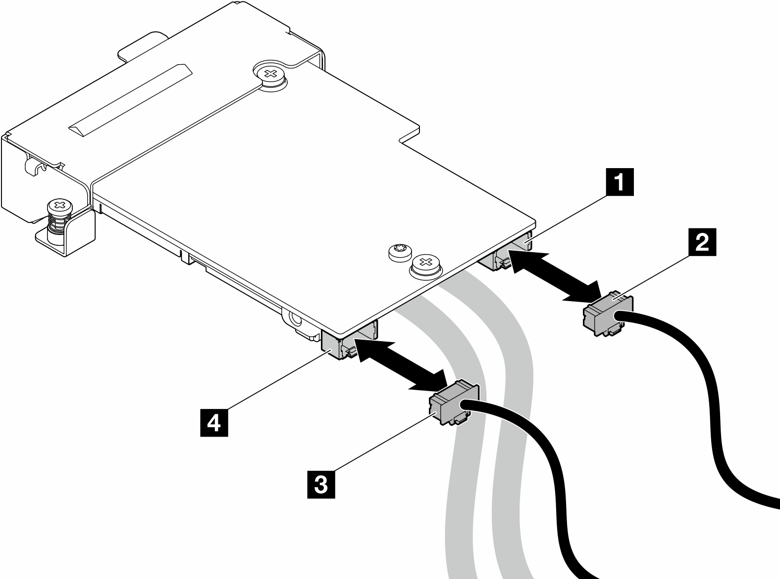
- Install the OSFP module.
 Align the OSFP module to the guide pins, and install the OSFP module to the compute node.
 Tighten the three screws to secure the OSFP module to the compute node.
Figure 3. OSFP module installation
- Connect the OSFP module cables to the network board on the GPU node.CAUTION
Hold the cable connector at 45 degree angle when inserting it into the port.
Have extremely precaution when reseating the connectors that have a 45 degree label on them as they are fragile and will get damage if not installed in the correct 45 degree angle.

Figure 4. Connecting the OSFP module cables to the network board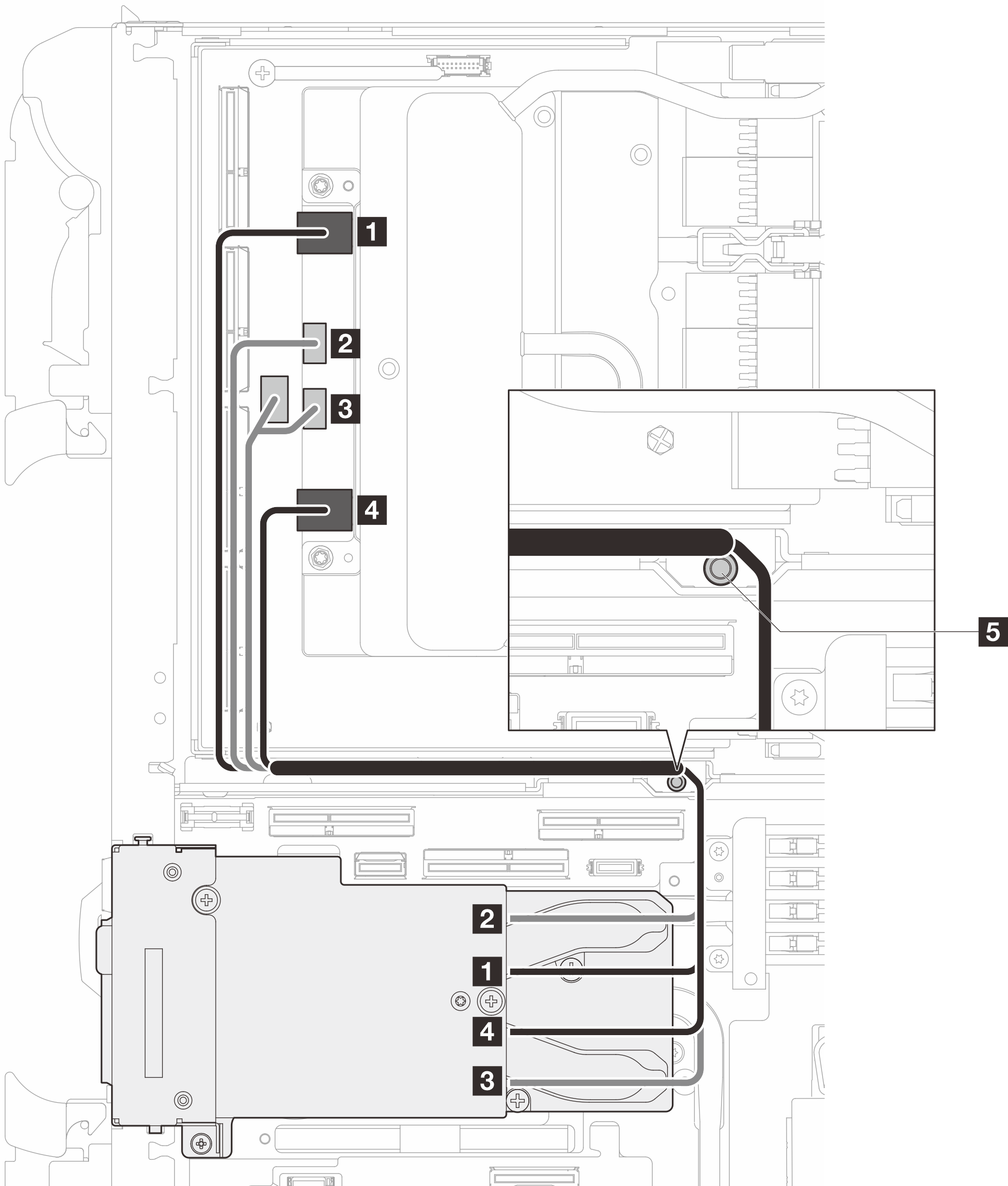
From OSFP module connectors
To Network board connectors
1 Network connector (near GPU node) 1 Port 0 2 Power connector P1 2 OOB port 0 3 Power connector P2 3 OOB port 1 (on network board) and power connector (on carrier board) 4 Network connector (near Compute node) 4 Port 1 5 Stud (in between the nodes) Make sure the cables are routed around the stud as shown in the illustration. - Connect MCIO 1, MCIO 2, and MCIO 3 cables to the carrier board.Figure 5. Two-processor configuration—Connecting MCIO 2, MCIO 3, and MCIO 4 cable to the GPU node
Make sure to follow the sequence 1 → 2 → 3.

From (carrier board in GPU node) To (system board in compute node) 1 MCIO 2 1 PCIe x 16 MCIO 4 connector 2 MCIO 3 2 PCIe x 16 MCIO 1 connector 3 MCIO 4 3 PCIe x 16 MCIO 2 connector 5 Stud (in between the nodes) Make sure the cables are routed around the stud as shown in the illustration. - Connect the drive cable.Figure 6. Drive assembly cable routing
 Figure 7. 7mm NVMe drive assembly cable routingFigure 8. E3.S drive cable routing
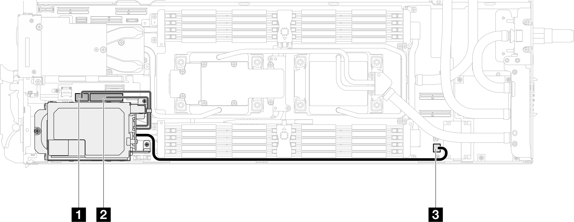
Install the M.2 backplane assembly. See Install the M.2 backplane assembly.
Install the cross braces. See Install the cross braces.
Install the tray cover. See Install the tray cover.
Install the tray into the enclosure. See Install a DWC tray in the enclosure.
- Connect all required external cables to the solution.NoteUse extra force to connect QSFP cables to the solution.
Check the power LED on each node to make sure it changes from fast blink to slow blink to indicate all nodes are ready to be powered on.