Remove the OSFP module
Use this information to remove the OSFP module.
About this task
Required tools
Make sure that you have the SD650-N V3 OSFP Putty Pad Kit to properly replace the component.
| Screw Type/Usage | Screwdriver Type |
|---|---|
| Hex screw | 4.5 mm hex head screwdriver |
| Releasing OSFP module from conduction plate | Flat head screwdriver |
Read Installation Guidelines and Safety inspection checklist to ensure that you work safely.
Turn off the corresponding DWC tray that you are going to perform the task on.
Disconnect all external cables from the enclosure.
- A video of this procedure is available at YouTube.
Procedure
- Disconnect the drive cage cable.Figure 1. Drive assembly cable routing
 Figure 2. 7mm NVMe drive assembly cable routingFigure 3. E3.S drive cable routing
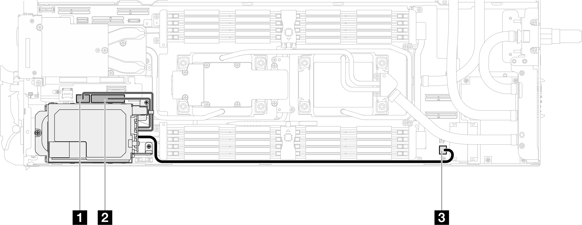
- Disconnect MCIO 2, MCIO 3, and MCIO 4 cables from carrier board.Figure 4. Disconnecting MCIO 2, MCIO 3, and MCIO 4 cables

From (carrier board in GPU node) To (system board in compute node) 1 MCIO 2 1 PCIe x 16 MCIO 4 connector 2 MCIO 3 2 PCIe x 16 MCIO 1 connector 3 MCIO 4 3 PCIe x 16 MCIO 2 connector 5 Stud (in between the nodes) Make sure the cables are routed around the stud as shown in the illustration. - Disconnect the OSFP module cables from the network board on the GPU node.CAUTION
Hold the cable connector at 45 degree angle when inserting it into the port.
Have extremely precaution when reseating the connectors that have a 45 degree label on them as they are fragile and will get damage if not installed in the correct 45 degree angle.
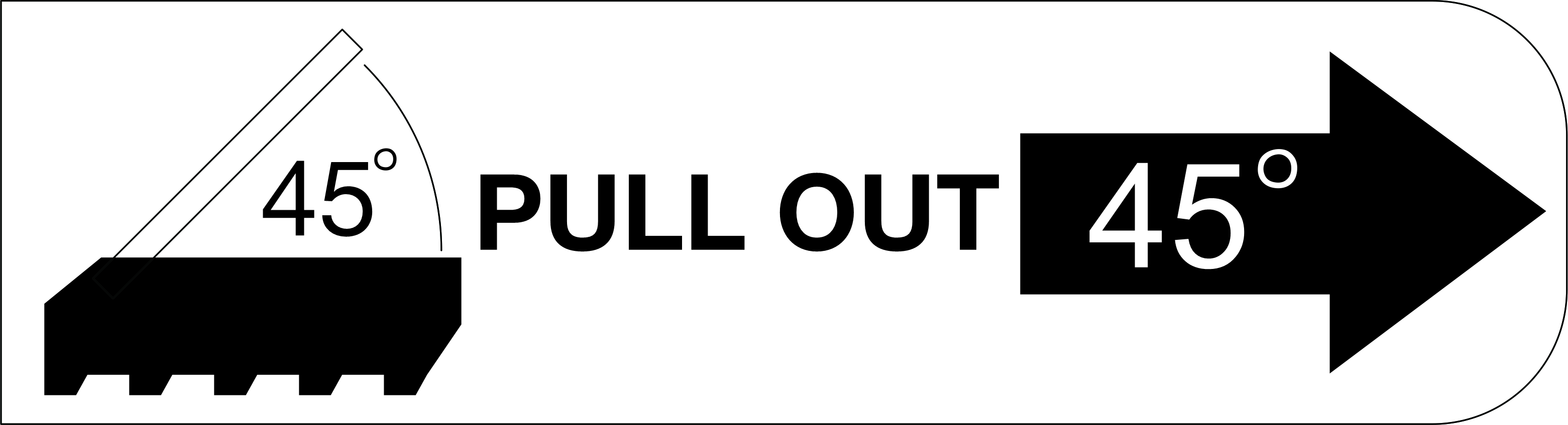
Figure 5. Disconnecting OSFP module cables from the network board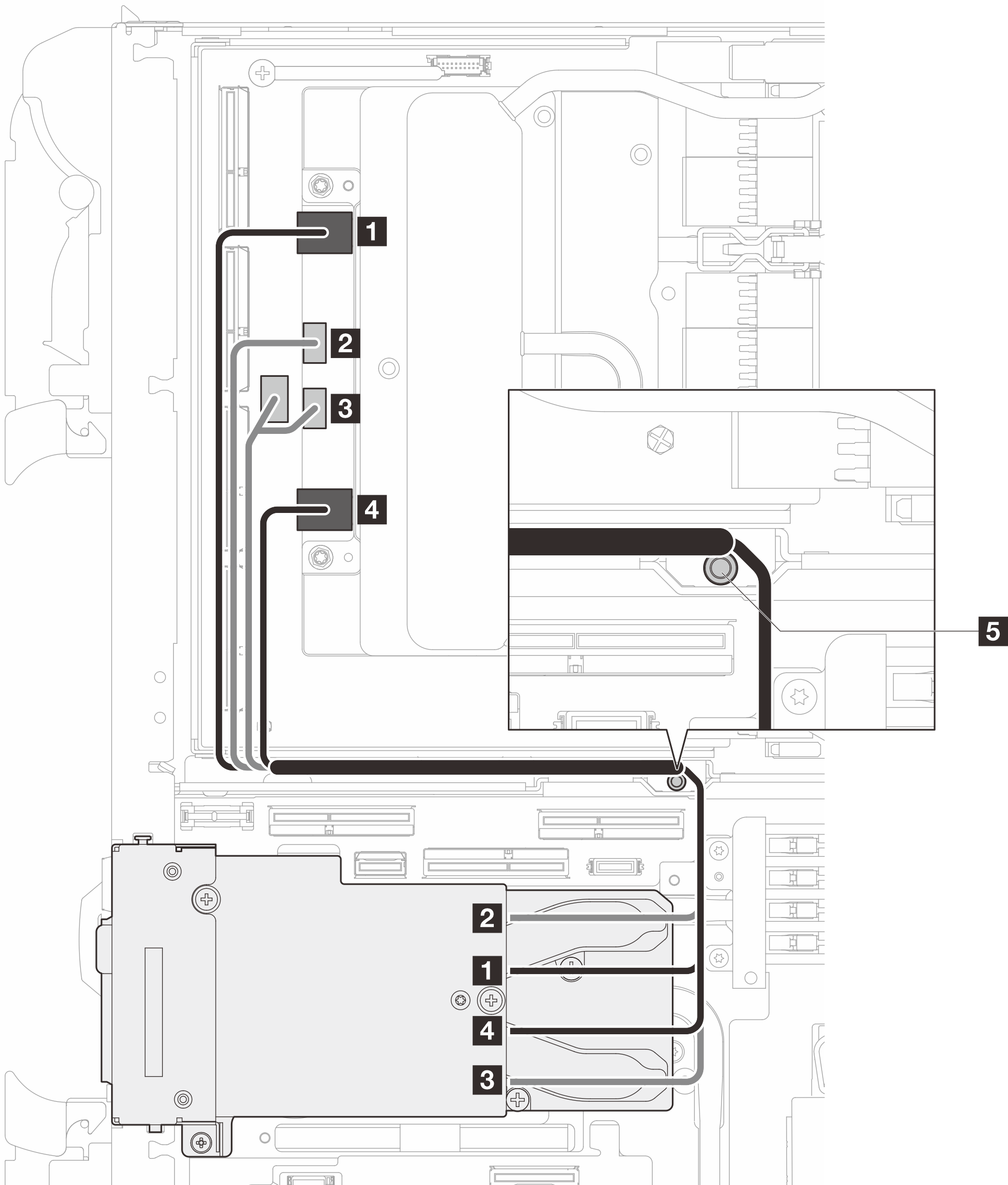
From OSFP module connectors
To Network board connectors
1 Network connector (near GPU node) 1 Port 0 2 Power connector P1 2 OOB port 0 3 Power connector P2 3 OOB port 1 (on network board) and power connector (on carrier board) 4 Network connector (near Compute node) 4 Port 1 5 Stud (in between the nodes) Make sure the cables are routed around the stud as shown in the illustration. - Remove the three screws from the OSFP module.Figure 6. Removing the OSFP module
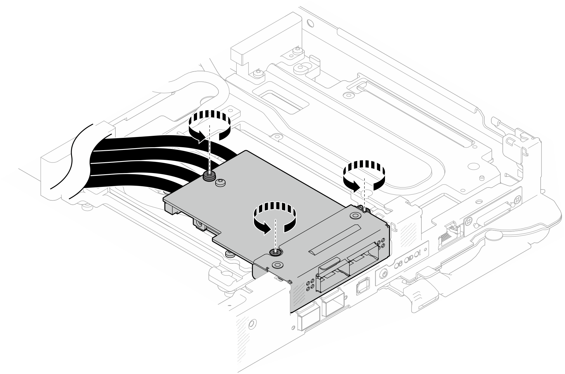
- Remove the OSFP module.
 Insert a flat head screwdriver into the gap between the OSFP module and the OSFP module conduction plate; then, rotate the flat head screwdriver to release the OSFP module from the conduction plate.
 Carefully hold the OSFP module by its edges and keep the OSFP module at an angle. Then, remove it from the compute node.
Figure 7. Removing the OSFP module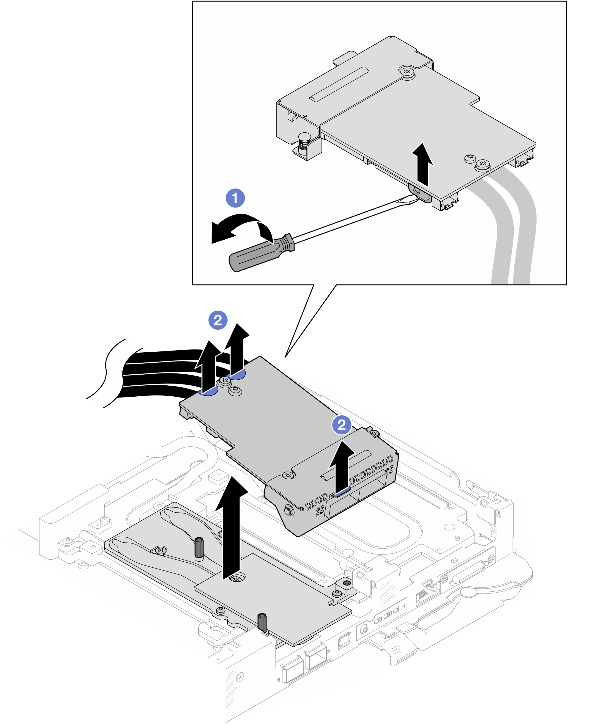
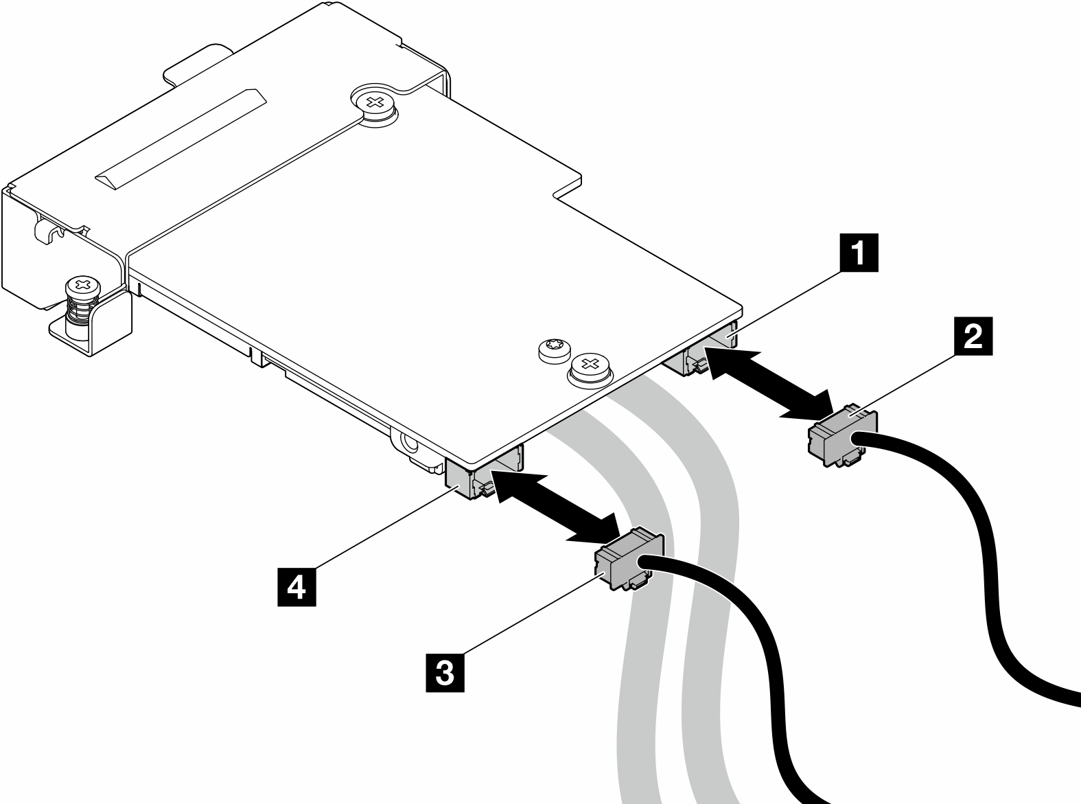
- Disconnect the power cables from the OSFP module.Figure 8. OSFP module power cables removal
If you are instructed to return the component or optional device, follow all packaging instructions, and use any packaging materials for shipping that are supplied to you.