Remove the system board
Use this information to remove the system board.
About this task

To avoid a shock hazard:
- Connect all power cords to a properly wired and grounded electrical outlet/source.
- Connect any equipment that will be attached to this product to properly wired outlets/sources.
- When possible, use one hand only to connect or disconnect signal cables.
- Never turn on any equipment when there is evidence of fire, water, or structural damage.
- The device might have more than one power cord, to remove all electrical current from the device, ensure that all power cords are disconnected from the power source.
- Read the following sections to ensure that you work safely.
- Turn off the corresponding DWC tray that you are going to perform the task on.NoteIf Shared I/O adapters are installed, power off the auxiliary node (node 1/3/5/7/9/11) first, and then power off the primary node (node 2/4/6/8/10/12).
- Disconnect all external cables from the enclosure.NoteUse extra forces to disconnect QSFP cables if they are connected to the solution.
To avoid damaging the water loop, always use the water loop carrier when removing, installing or folding the water loop.
| Screwdriver type | Screw type |
| Torx T10 head screwdriver | Torx T10 screw |
| Torx T30 head screwdriver | Torx T30 screw |
| Phillips #1 head screwdriver or 3/16" hex head screwdriver | Phillips #1 screw |
| Phillips #2 head screwdriver | Phillips #2 screw |
| 3/16" hex head screwdriver | Hex head screw |
| 2.5x0.4 mm Flat head screwdriver | 2.5x0.4 mm flat head screwdriver |
Procedure
- Make preparations for this task.
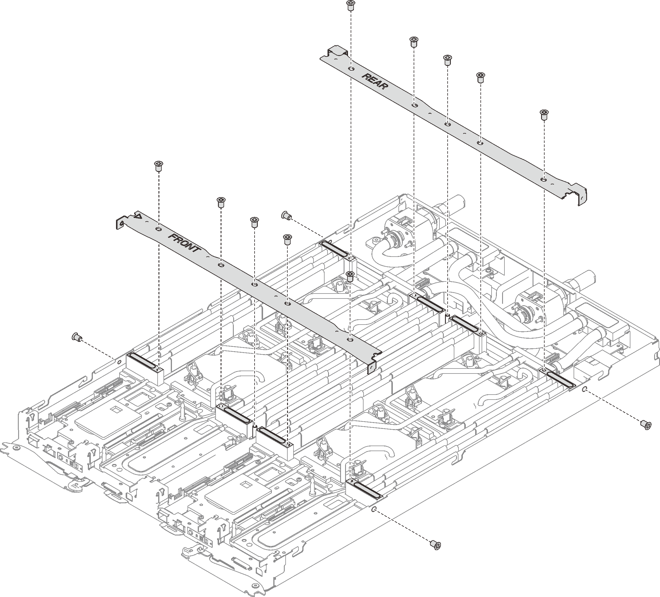
- Remove the front and the rear cross braces (14x Phillips #1 screws).Figure 1. Cross brace removal
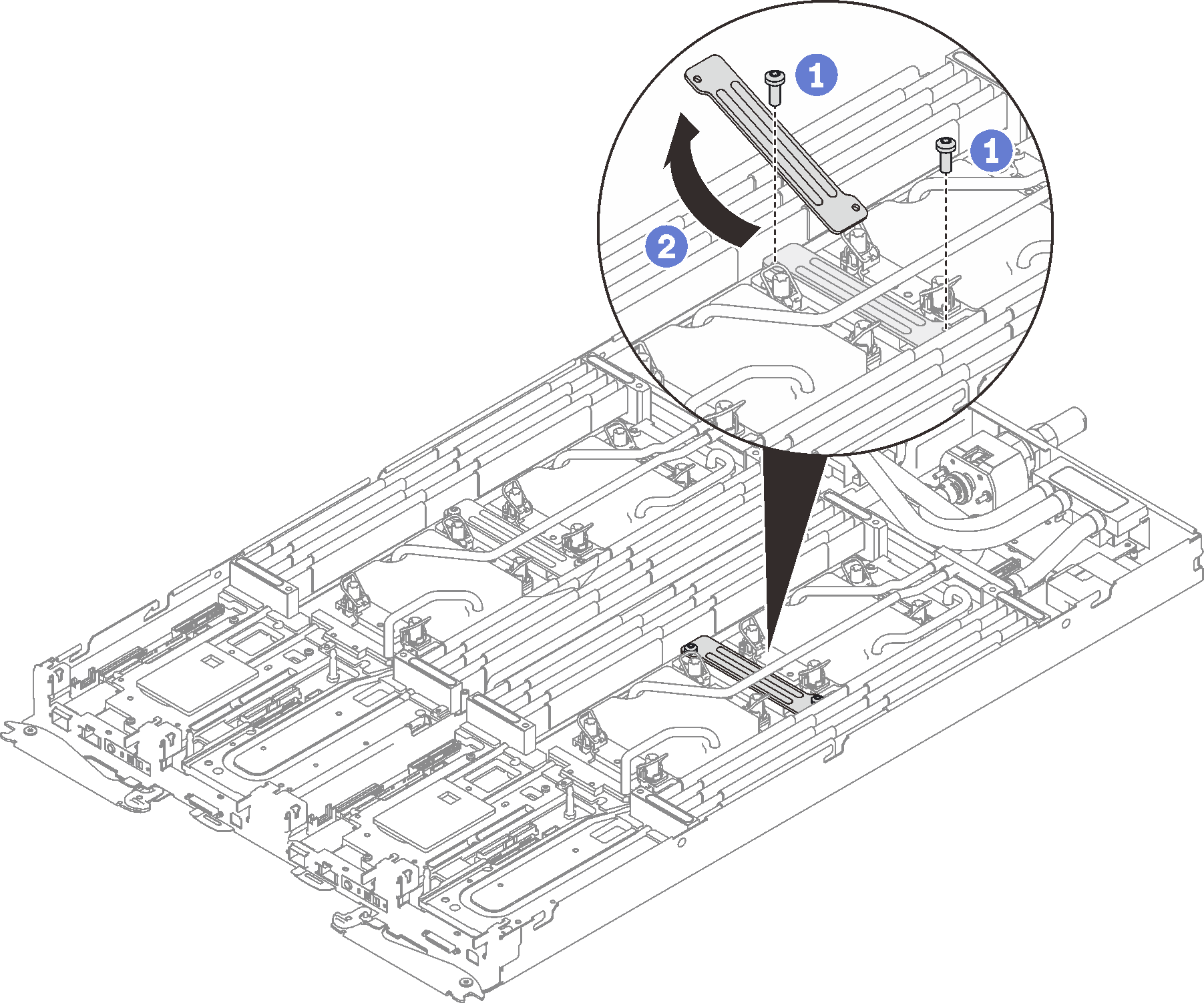
- Remove two Torx T10 screw (per node); then, slide the VR clamp plate out of the node.Figure 2. VR clamp plate removal
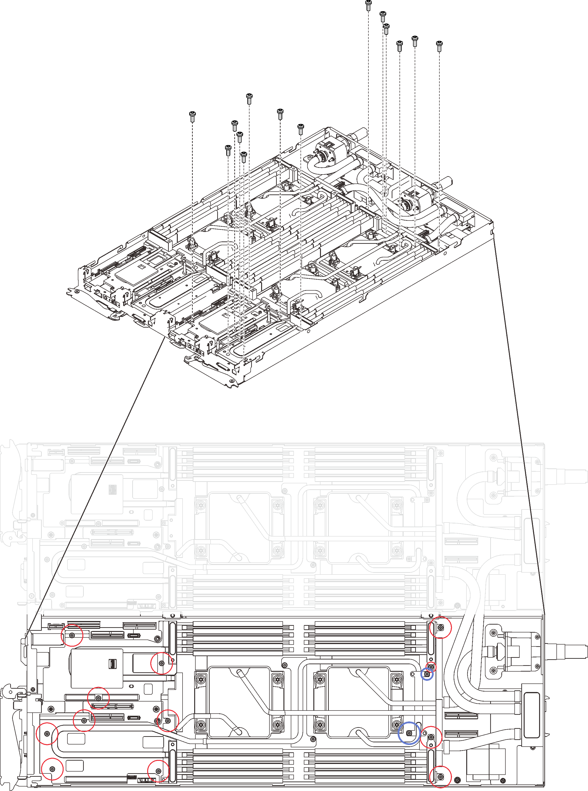
- Remove water loop screws (13x Torx T10 screws per node) with a torque screwdriver sets to the proper torque.NoteFor reference, the torque required for the screws to be fully tightened/removed is 0.5-0.6 newton-meters, 4.5-5.5 inch-pounds.Figure 3. Water loop screws removal
- Remove the following screws to loosen the quick connect.
Four Torx T10 screws (per node) to loosen the quick connect.
Two Phillips #1 screws (per node) on the rear of the node.
Figure 4. Screws removal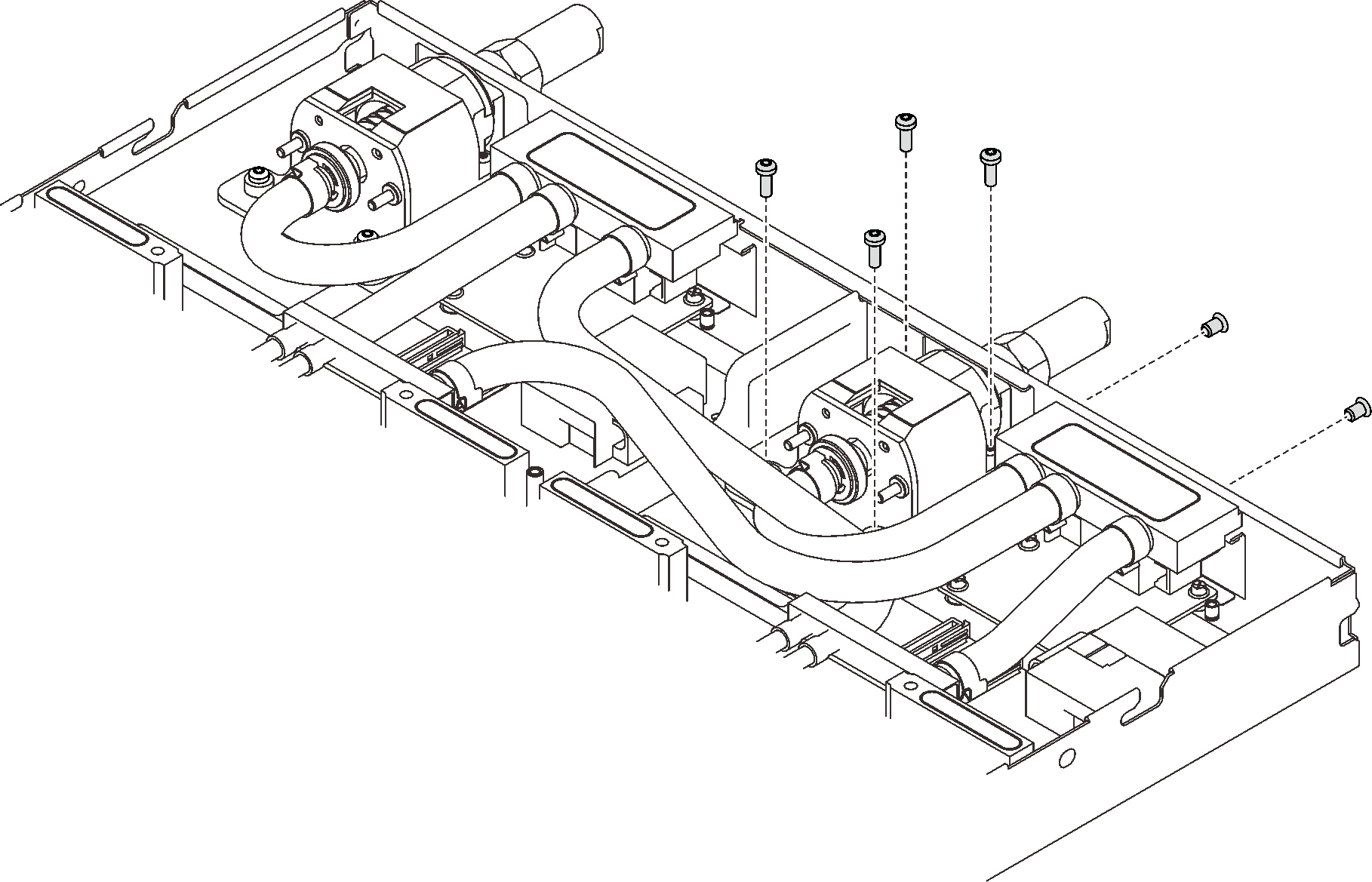
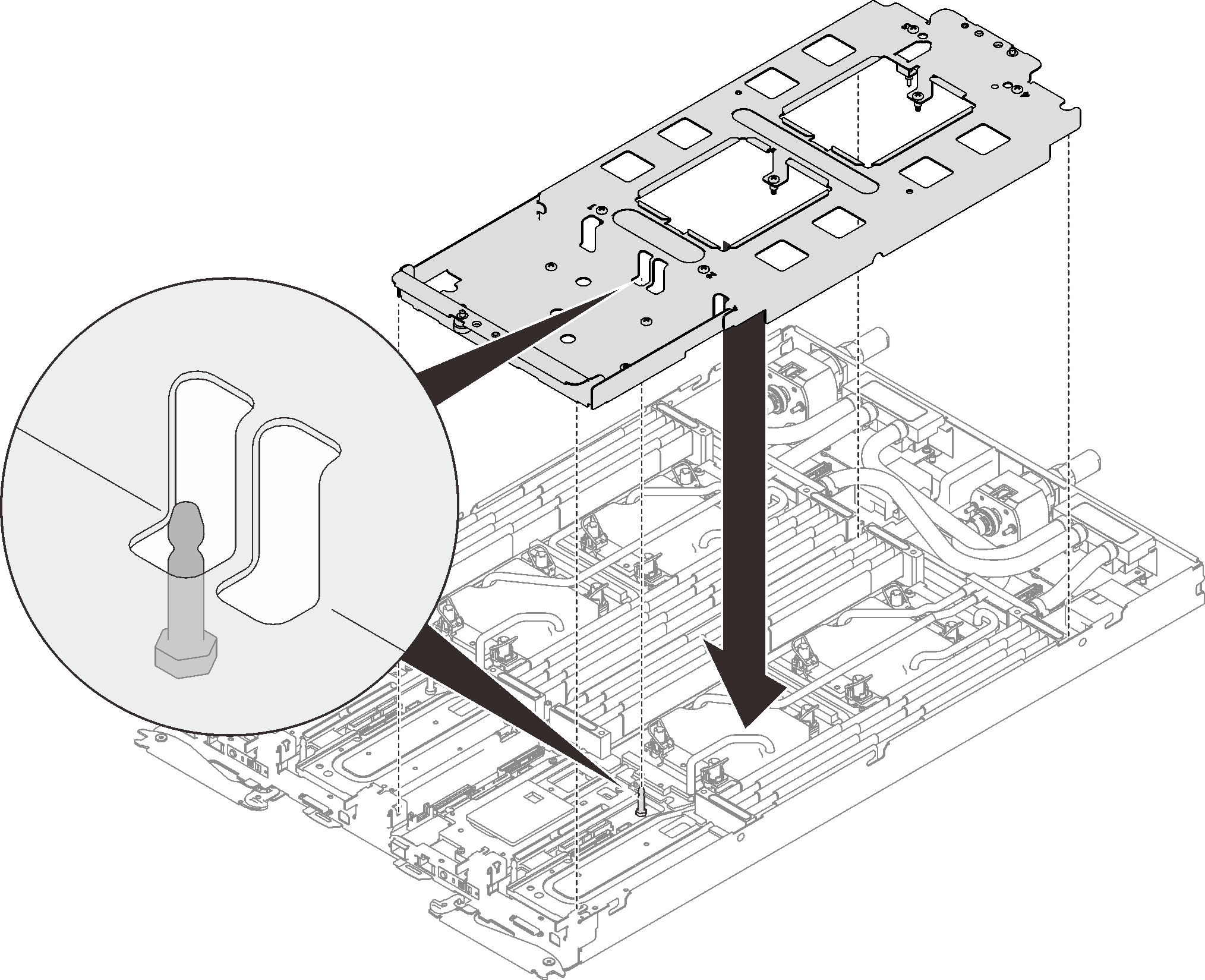
- Orient the water loop carrier with the M.2 backplane guide pin; then, gently put the water loop carrier down and ensure it is seated firmly on the water loop.Figure 5. Water loop carrier installation
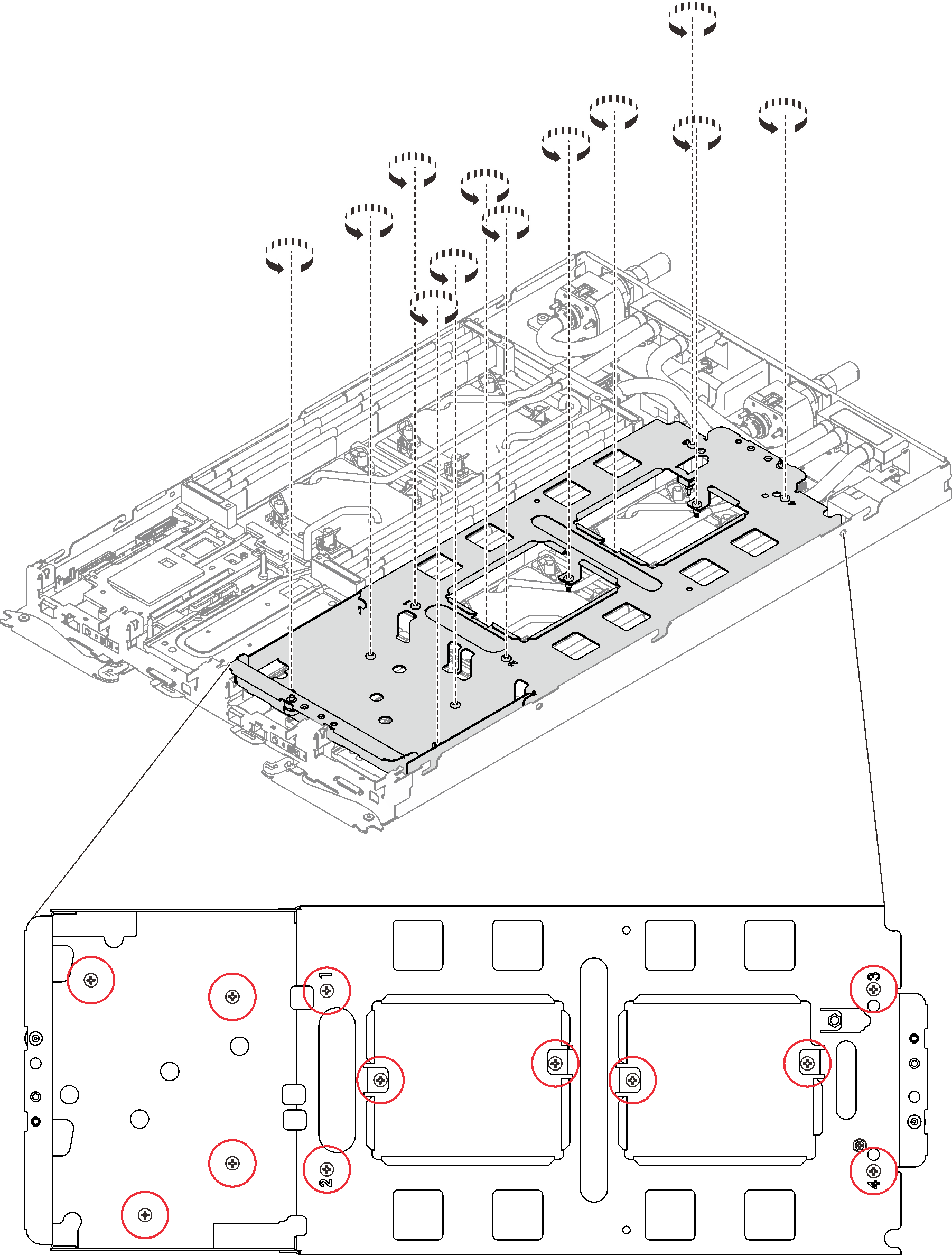
- Tighten water loop carrier screws (12x Phillips #2 screws per node).Figure 6. Water loop carrier screws installation
- Loosen processors properly.
❶ Fully loosen all Torx T30 captive screws (8x Torx T30 captive screws per node) on cold plates in the removal sequence shown on the cold plate label (with a torque screwdriver sets to the proper torque).
NoteFor reference, the torque required for the screws to be fully tightened/removed is 1.1-1.15 newton-meters, 9.8-10.2 inch-pounds.AttentionTo prevent damage to components, make sure that you follow the indicated loosening sequence.❷ Rotate all anti-tilt wire bails (8x anti-tilt wire bails per node) inwards to the unlocked position.
Figure 7. Loosening processors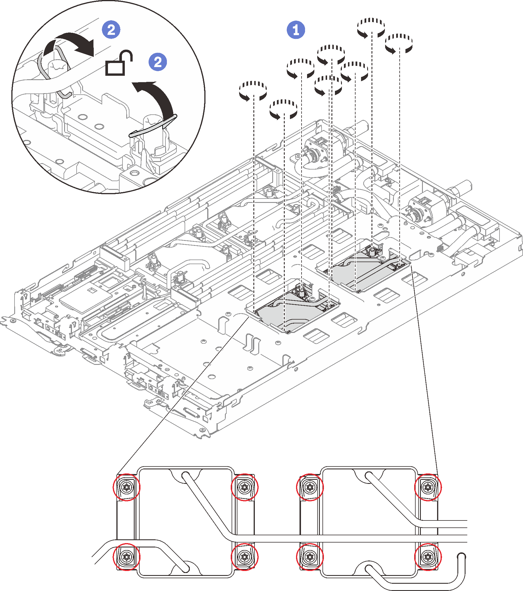
- Fold the water loop.
❶ Carefully unhook the quick connect and slide it out of the opening in the rear of the tray; then, lift the water loop up off the system board.
❷ Carefully rotate the water loop so one half is sitting on top of the other half.
Figure 8. Folding the water loop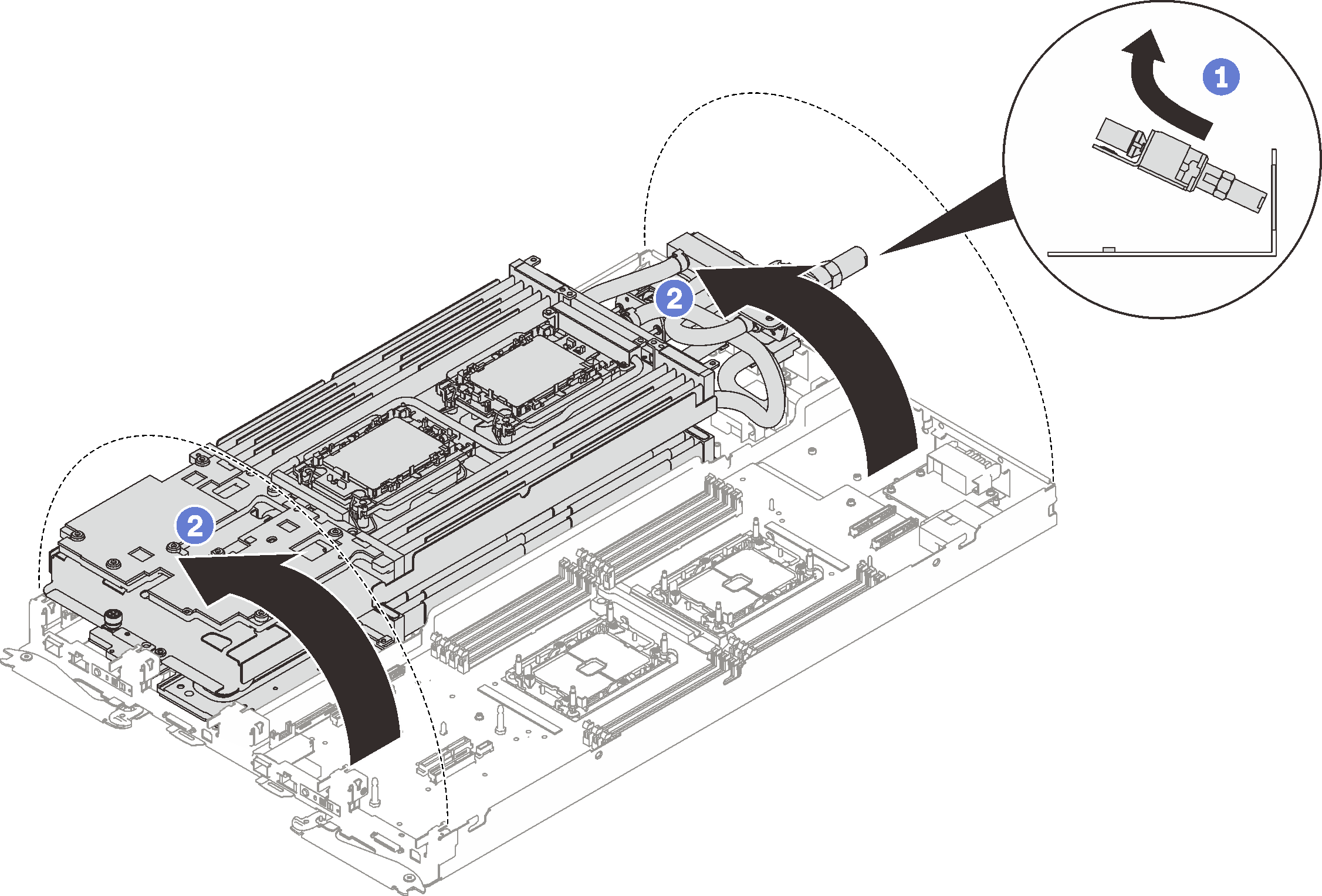
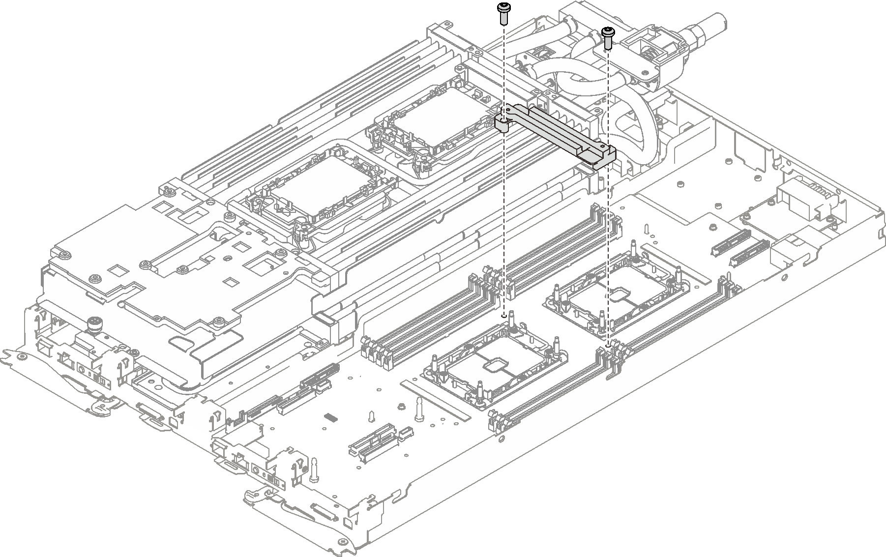
- Remove the twoTorx T10 screws (per node) to remove the VR water loop trough out of the system board.Figure 9. VR water loop trough removal
- Remove the front and the rear cross braces (14x Phillips #1 screws).
- Remove the following screws.
Five Phillips #1 screws per node on the system board (with a torque screwdriver sets to the proper torque).
NoteFor reference, the torque required for the screws to be fully tightened/removed is 0.5-0.6 newton-meters, 4.5-5.5 inch-pounds.- Two jackscrews per node at the front of the node.Note
Use 2.5x0.4 mm Flat head screwdriver to remove and install jackscrews.
For reference, the torque required for the screws to be fully tightened/removed is 0.059 newton-meters, 0.52 inch-pounds.
Figure 10. 2.5x0.4 mm Flat head screwdriver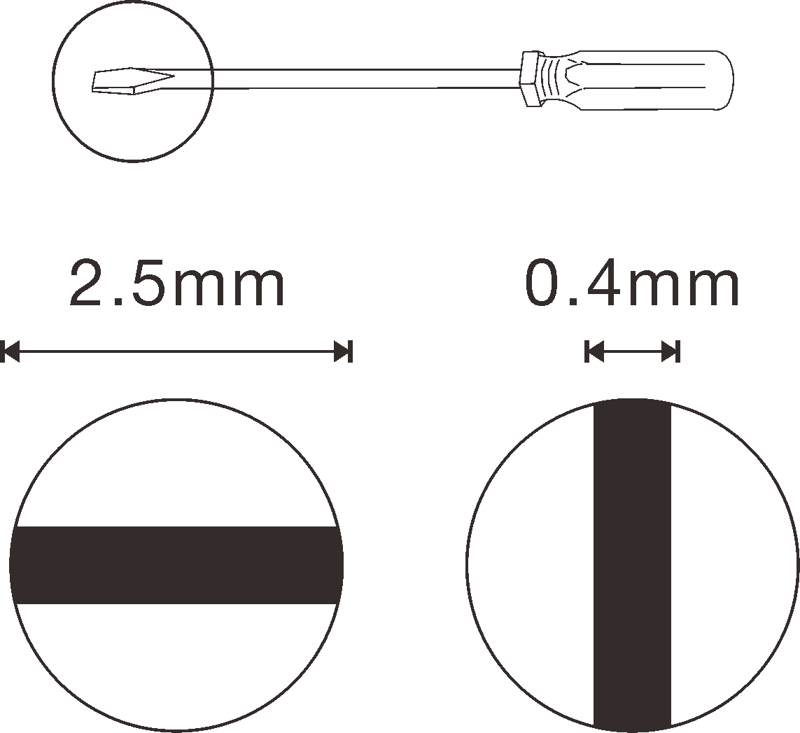 Figure 11. Screws removal
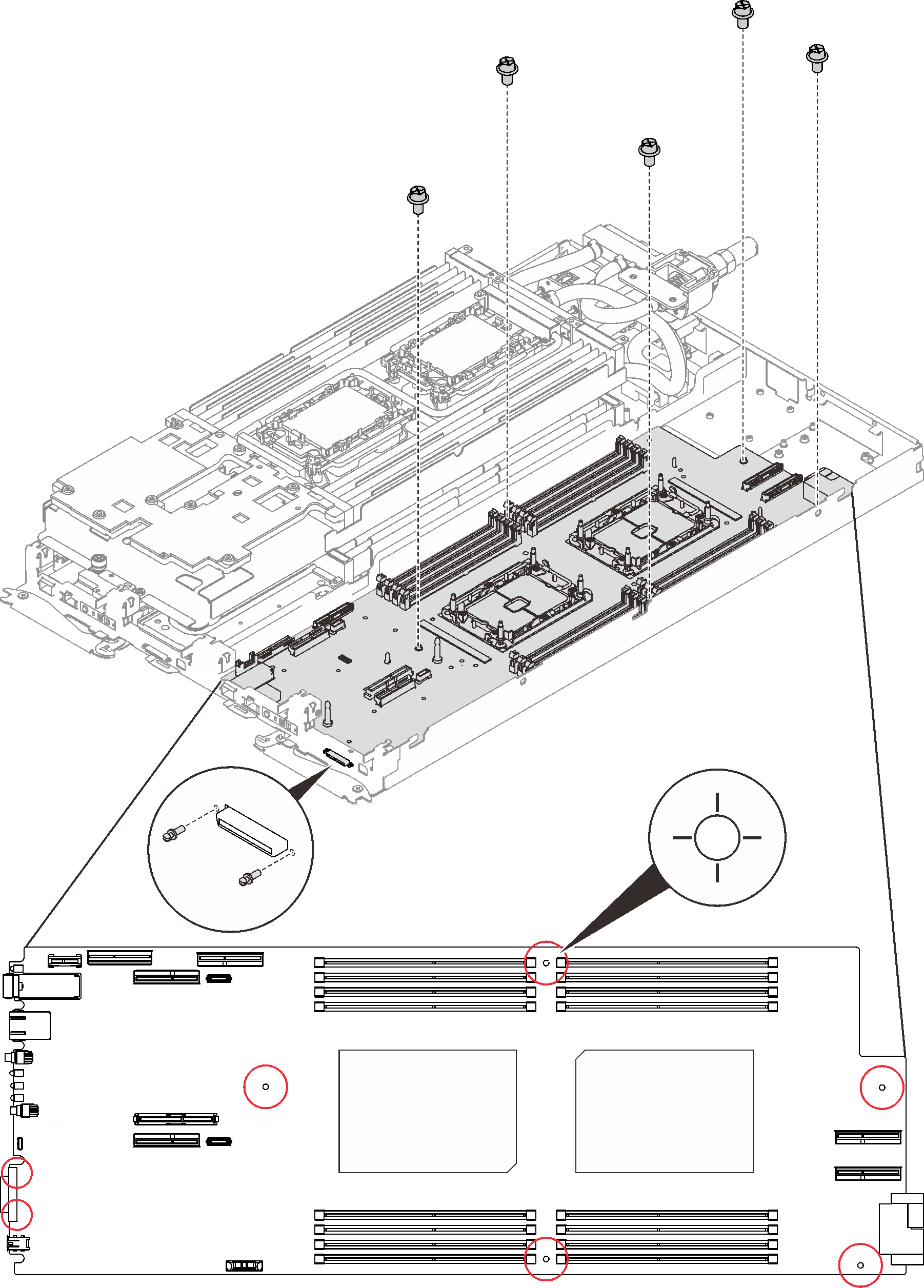
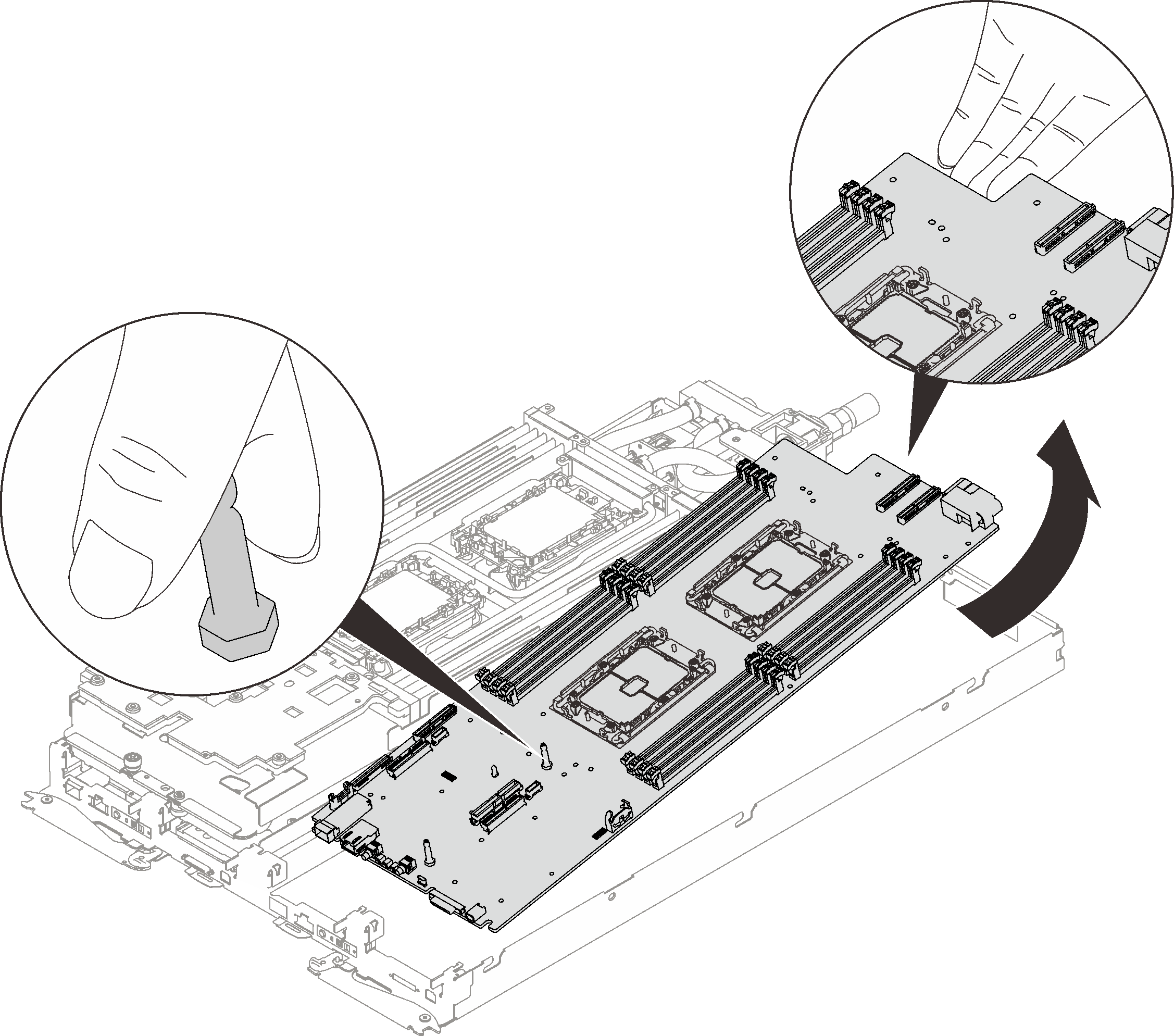
- Gently slide the system board backward; then, carefully lift and remove the system board from the node.NoteWhen you remove the system board from the node, avoid touching the connectors on the system board. Be careful not to damage any surrounding components inside the node.Figure 12. System board removal
If you are instructed to return the component or optional device, follow all packaging instructions, and use any packaging materials for shipping that are supplied to you.
Take a dust cover from the processor socket assembly on the new system board and orient it correctly above the processor socket assembly on the removed system board.
Gently press down the dust cover legs to the processor socket assembly, pressing on the edges to avoid damage to the socket pins. You might hear a click on the dust cover is securely attached.
Make sure that the dust cover is securely attached to the processor socket assembly.
Remove the two guide pins out of the system board.
Figure 13. Guide pins removal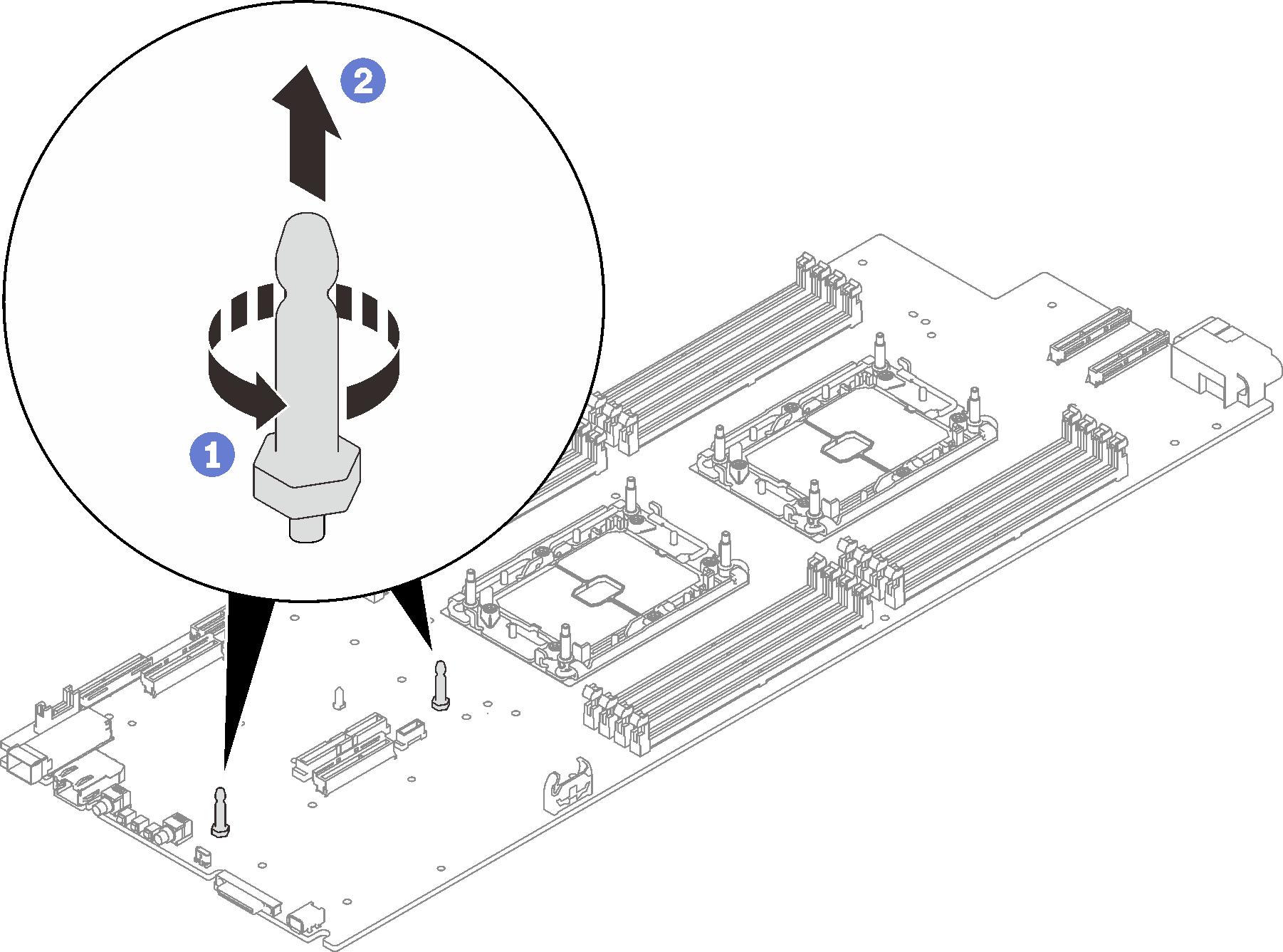
Recycle the unit in compliance with local regulations.
Demo video