Install an E3.s drive
Use this information to install an E3.s drive.
About this task
To identify the gap pad/putty pad location and orientation, see:
Required Tools list in the following section.
Before replacing the gap pad/putty pad, gently clean the interface plate or the hardware surface with an alcohol cleaning pad.
Hold the gap pad/putty pad carefully to avoid deformation. Make sure no screw hole or opening is blocked by the gap pad/putty pad material.
Do not use expired putty pad. Check the expiry date on putty pad package. If the putty pads are expired, acquire new ones to properly replace them.
Required tools
Make sure you have the required tools listed below in hand to properly replace the component.
E3.S Drive Conduction Plate Assembly
E3S Putty Pad Kit
E3S Gap Pad Kit
Putty pad cannot be reused. Whenever a component is removed, putty pads must be replaced with new ones before reinstalling the component.
Read Installation Guidelines and Safety inspection checklist to ensure that you work safely.
Procedure
- Install the top E3.s drive to the E3.s drive cage.
 Orient the E3.s drive so that the connector is on the right side as shown. Then, place the E3.s drive into the E3.s drive cage.
 Fasten the two screws to secure the E3.s drive to the E3.s drive cage
Figure 1. Top E3.s drive installation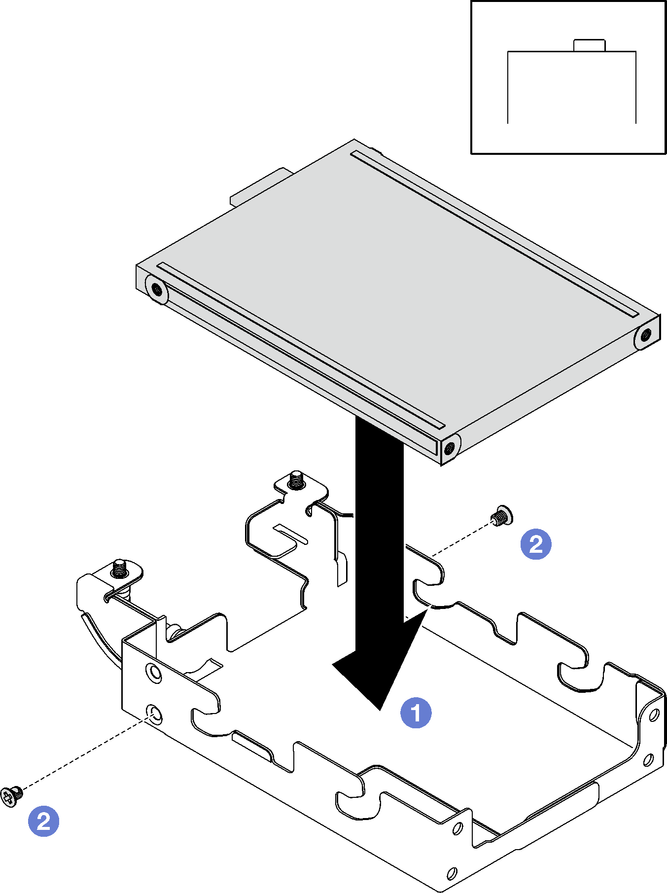
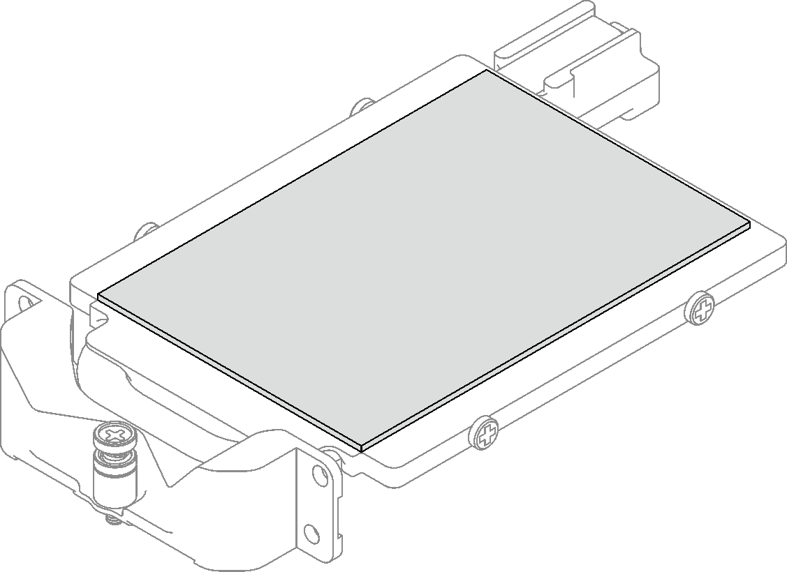
- If the gap pad located on the conduction plate is damaged or detached, discard the conduction plate. Then, install a new conduction plate already attached with the gap pad.Figure 2. Replacing the conduction plate gap pad
- Replace the putty pads on the conduction plate with new ones. Make sure to follow Gap pad/putty pad replacement guidelinesAttention
Putty pad cannot be reused. Whenever a component is removed, putty pads must be replaced with new ones before reinstalling the component.
Figure 3. Replacing the conduction plate putty pads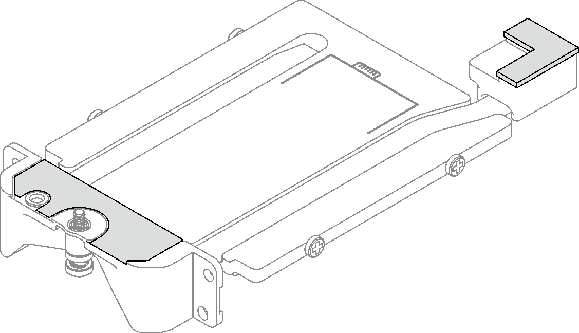
- Install the conduction plate to the drive cage.
- Hold the conduction plate at an angle; then, insert the conduction plate into the E3.s drive cage.
- Fasten the two screws to secure the conduction plate to the E3.s drive cage.
Figure 4. E3.s drive conduction plate installation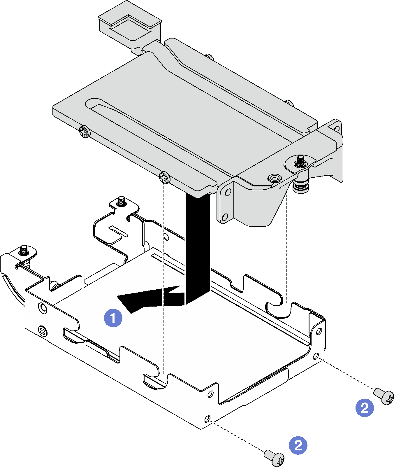
- Install the bottom E3.s drive.
- Orient the E3.s drive so that the connector is on the left side as shown. Then, place the bottom E3.s drive into the E3.s drive cage.
- Fasten the four screws to secure the bottom E3.s drive to the E3.s drive cage.
Figure 5. Bottom E3.s drive installation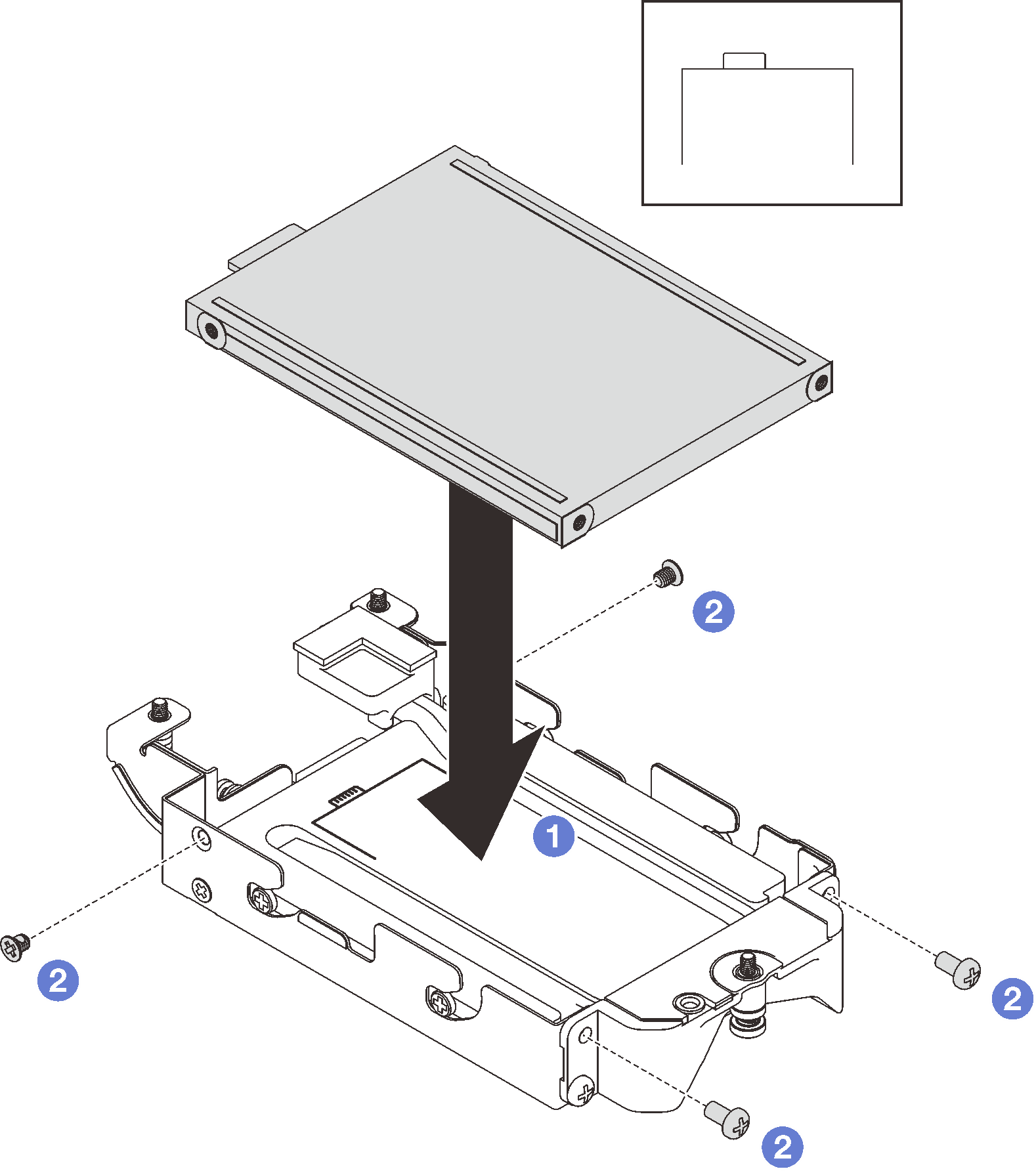
- Install the E3.s drive cable-ended backplane.
- Align the backplane to the screw hole on the E3.s drive cage; then, insert the backplane to the E3.s drive cage.
- Fasten the screw to secure the backplane to the E3.s drive cage.
Figure 6. E3.s cable-ended backplane installation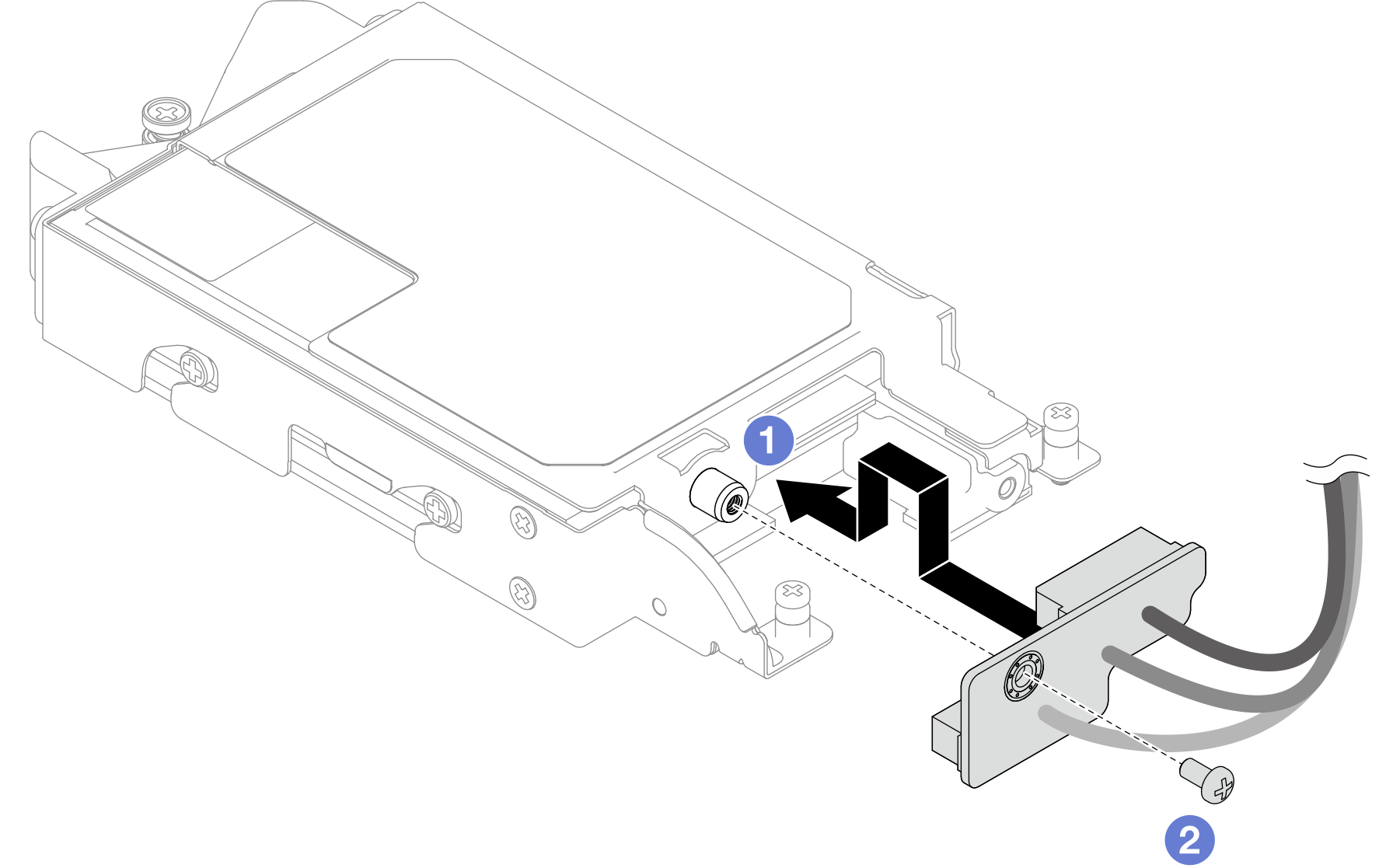
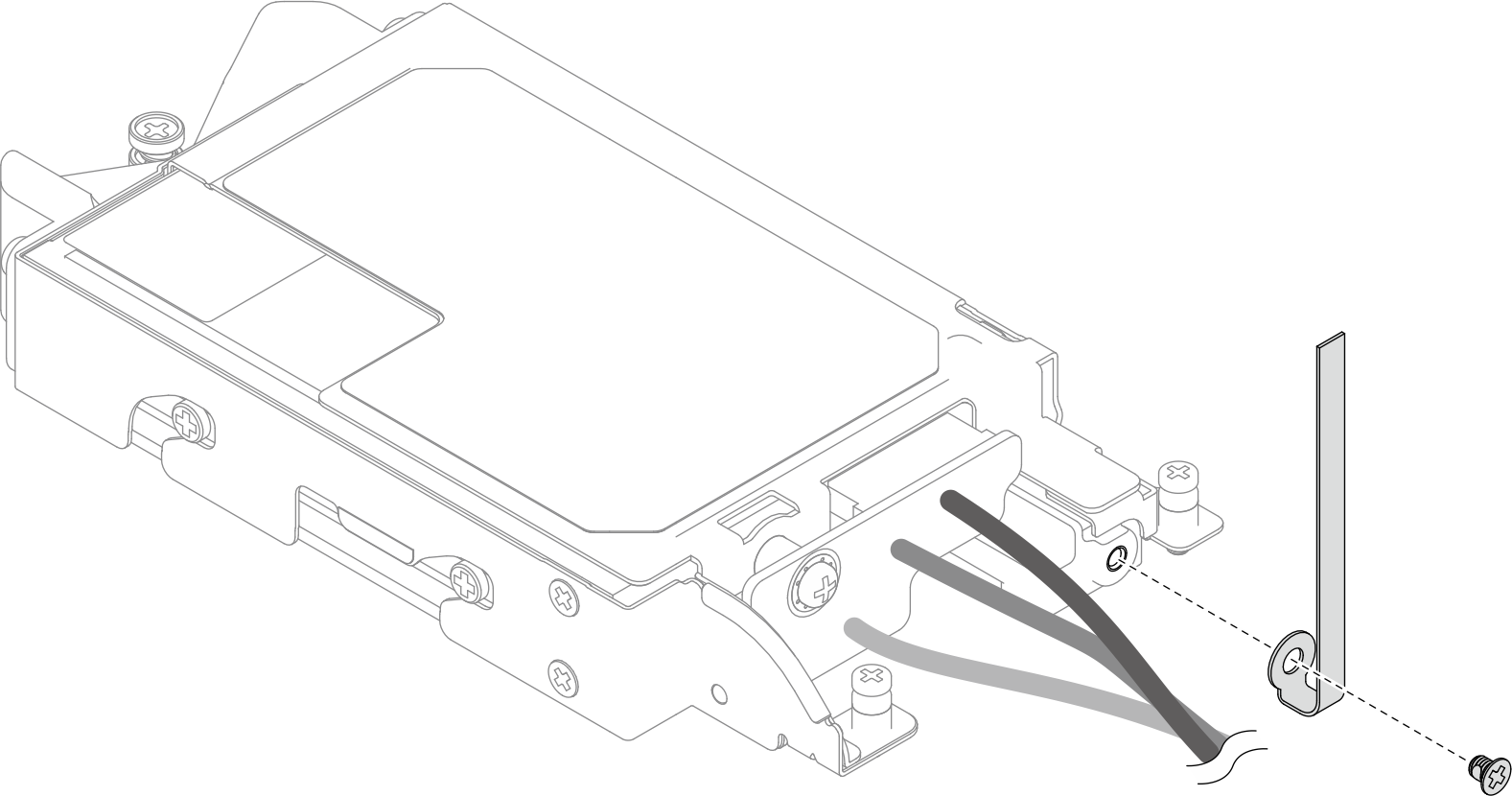
- Fasten the screw to install the cable tie to the E3.s drive cage.Figure 7. Cable tie installation
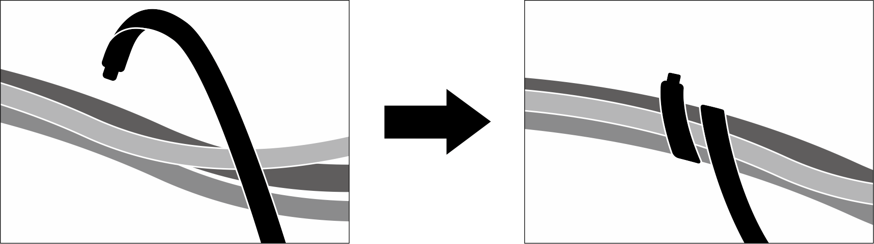
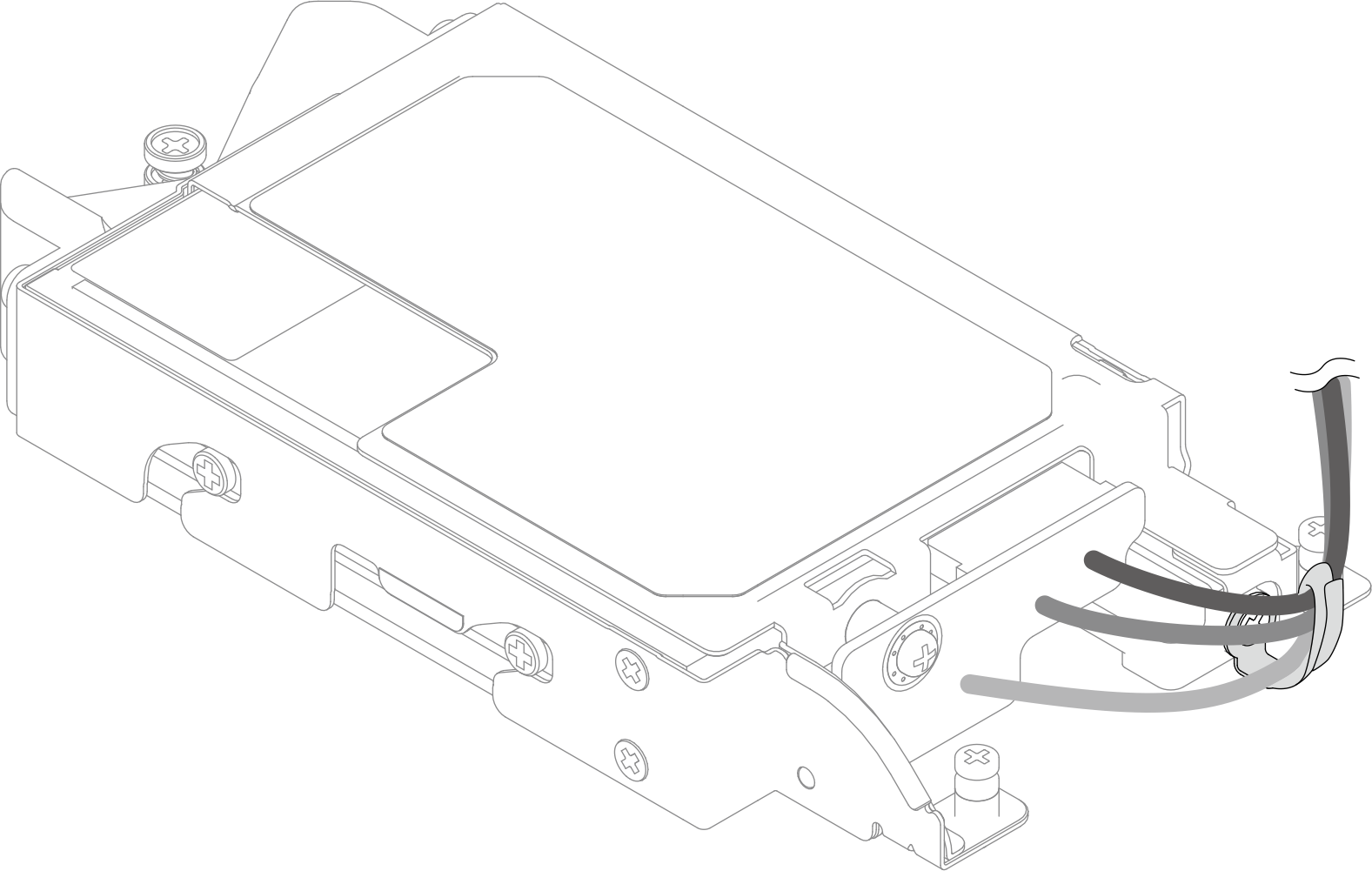
- Bundle the cables on the E3.s drive cable-ended backplane with the cable tie.Figure 8. Bundling cables with cable tie
Install the E3.s drive cage. See Install the E3.s drive cage assembly.
Install the cross braces. See Install the cross braces.
Install the tray cover. See Install the tray cover.
Install the tray into the enclosure. See Install a DWC tray in the enclosure.
- Connect all required external cables to the solution.NoteUse extra force to connect QSFP cables to the solution.
Check the power LED on each node to make sure it changes from fast blink to slow blink to indicate all nodes are ready to be powered on.
Demo video