Cheminement des câbles du nœud dans le boîtier
Suivez les instructions de la présente section afin de savoir comment procéder au cheminement des câbles du nœud dans un boîtier.
Remarque
Connexions entre les connecteurs : 1↔1, 2↔2, 3↔3, ... n↔n
Lorsque vous acheminez les câbles, assurez-vous que tous les câbles sont acheminés correctement grâce aux guides-câbles et aux clips de fixation.
Lorsque des nœuds ThinkEdge SE100 sont installés dans un boîtier 1U2N ou 1U3N, assurez-vous que les câbles des connecteurs d’E-S arrière et les câbles du kit d’extension sont correctement acheminés. Procédez comme suit pour acheminer les câbles du nœud dans le boîtier.
Procédure
- Retirez les composants suivants qui sont installés sur le boîtier et placez-les dans un endroit sûr et antistatique.
Retirez la traverse du boîtier.
 Desserrez les deux vis imperdables qui maintiennent la traverse.
 Tenez la traverse et retirez-la du boîtier.
Figure 1. Retrait de la traverse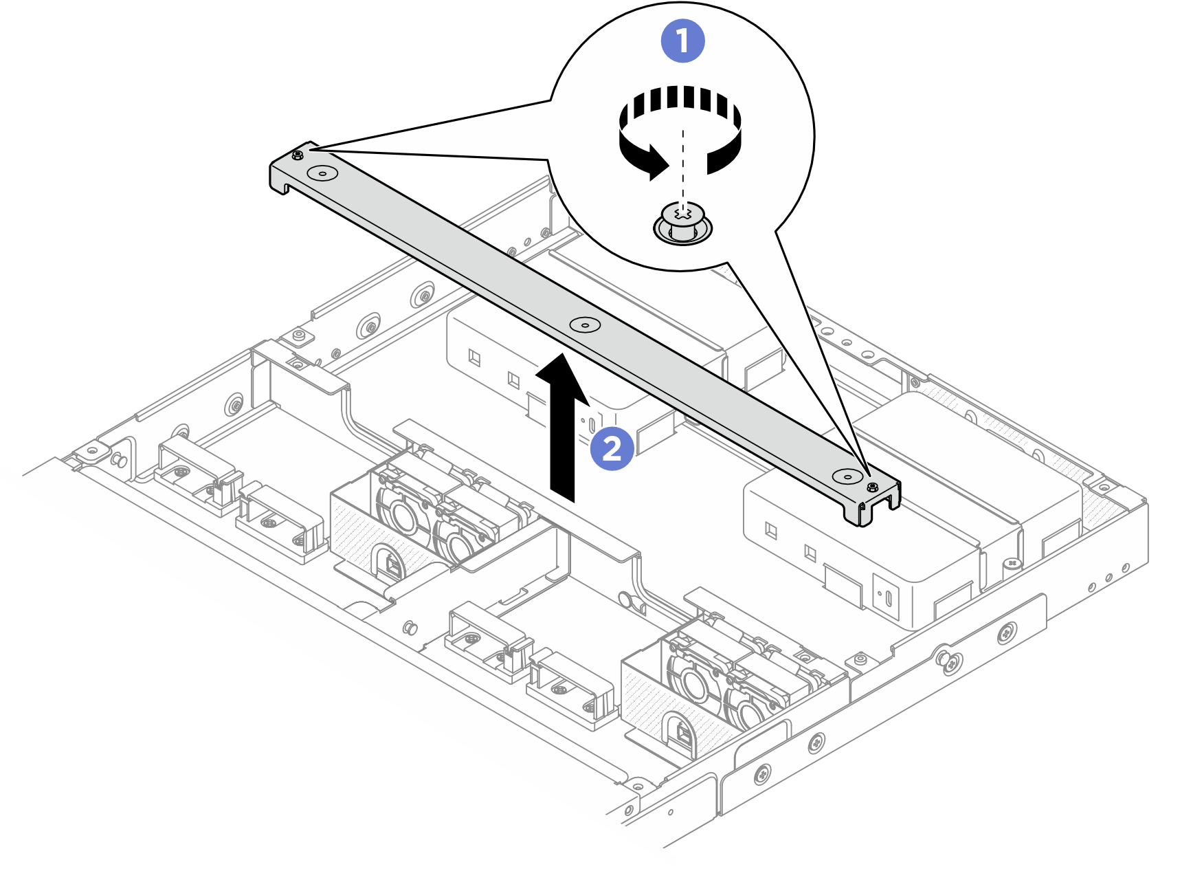
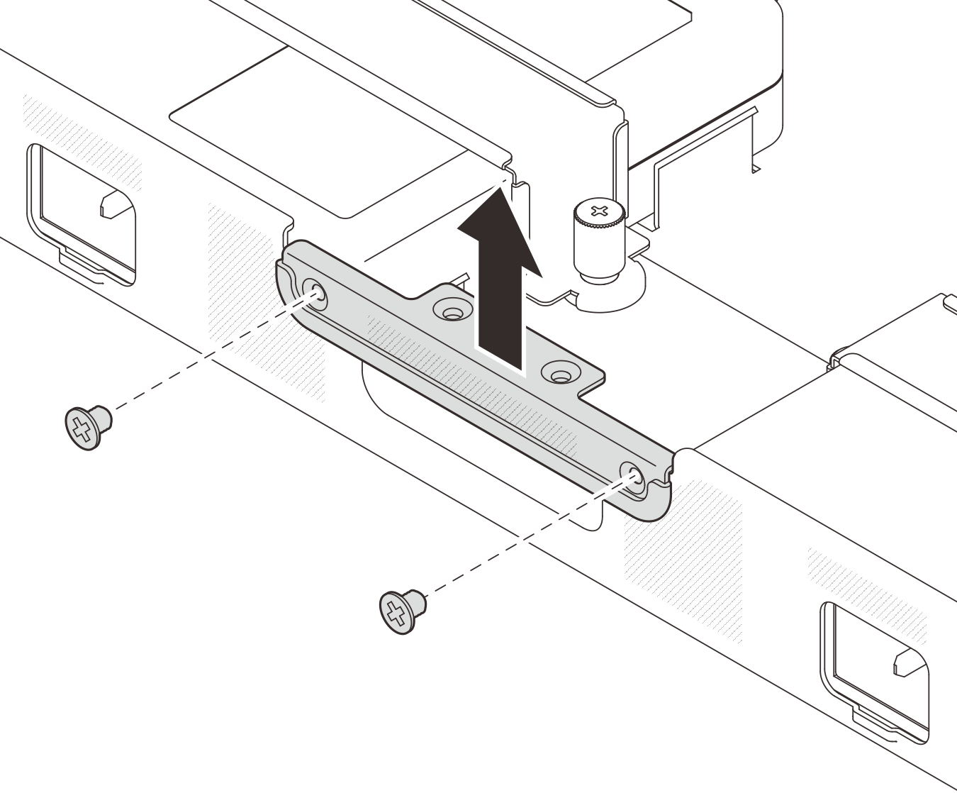
- Desserrez les deux vis qui fixent le support arrière, puis retirez-le du boîtier.Figure 2. Retrait du support arrière du boîtier
- Assurez-vous que les câbles concernés passent par les clips de fixation et les guide-câbles, comme illustré ci-dessous :Figure 3. Cheminement des câbles du nœud dans le boîtier 1U2N
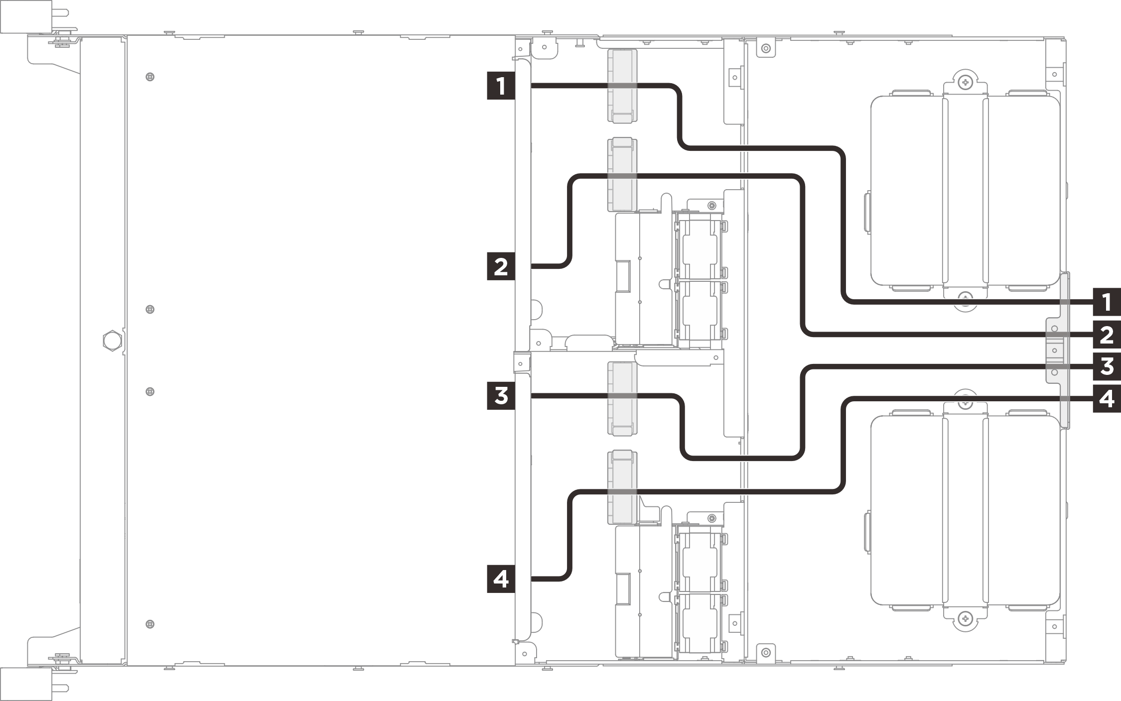
Nœud Câble Nœud de la baie 1 1 Câbles du kit d’extension 2 Câbles provenant des connecteurs d’E-S arrière du nœud Nœud de la baie 2 3 Câbles du kit d’extension 4 Câbles provenant des connecteurs d’E-S arrière du nœud Figure 4. Cheminement des câbles du nœud dans le boîtier 1U3N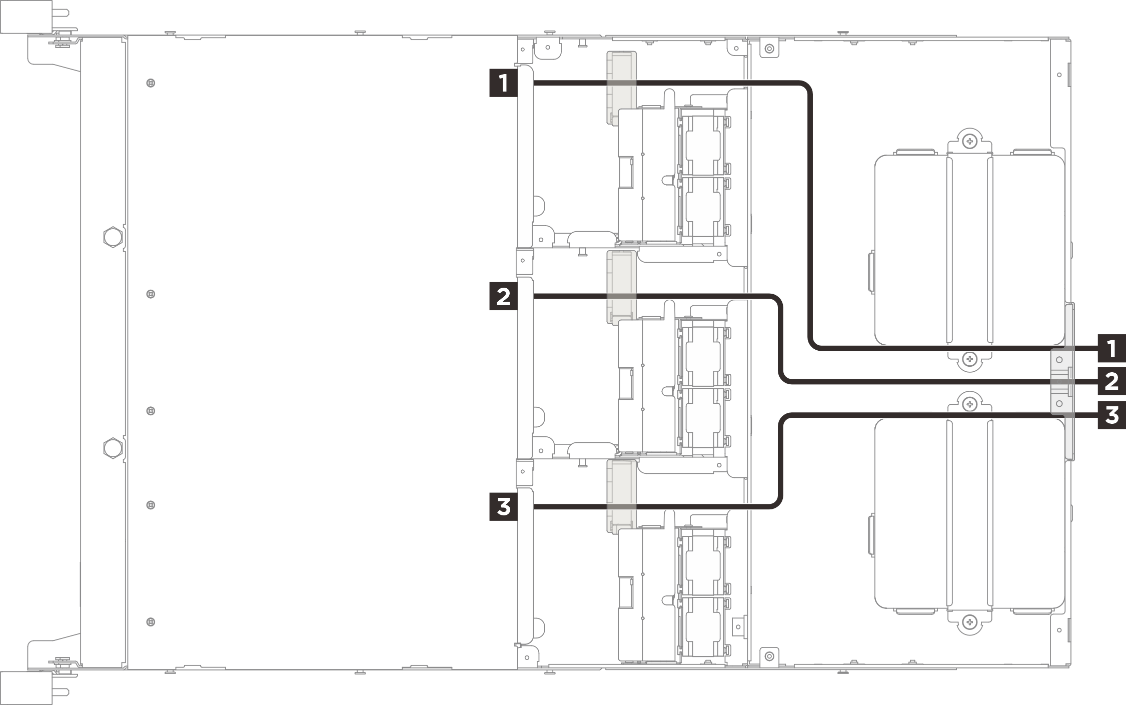
Nœud Câbles provenant des connecteurs d’E-S arrière du nœud Nœud de la baie 1 1 Nœud de la baie 2 2 Nœud de la baie 3 3
Envoyer des commentaires