Install the I/O module board and M.2 boot drives
Follow instructions in this section to install the I/O board and M.2 boot drives.
About this task
S002
CAUTION
The power-control button on the device and the power switch on the power supply do not turn off the electrical current supplied to the device. The device also might have more than one power cord. To remove all electrical current from the device, ensure that all power cords are disconnected from the power source.
Attention
Read Installation Guidelines and Safety inspection checklist to ensure that you work safely.
Touch the static-protective package that contains the component to any unpainted metal surface on the server; then, remove it from the package and place it on a static-protective surface.
The following notes describe the type of drives that the server supports and other information that you must consider when you install a drive. For a list of supported drives, see Lenovo ServerProven website.
- Locate the documentation that comes with the drive and follow those instructions in addition to the instructions in this chapter.
- For a complete list of supported optional devices for the server, see Lenovo ServerProven website.
- SE360 V2 supports up to two 80mm (2280) NVMe M.2 boot drives.
Install the I/O-board power and signal cable
If necessary, route the I/O-board power cable and signal cable.
Procedure
- Connect the I/O-board power cable and signal cable to the system board; then, route the cables through the chassis hole to the bottom side of the node.NoteMake sure to route the I/O-board power cable between the standoff and the chassis as shown.Figure 1. I/O-board cable routing
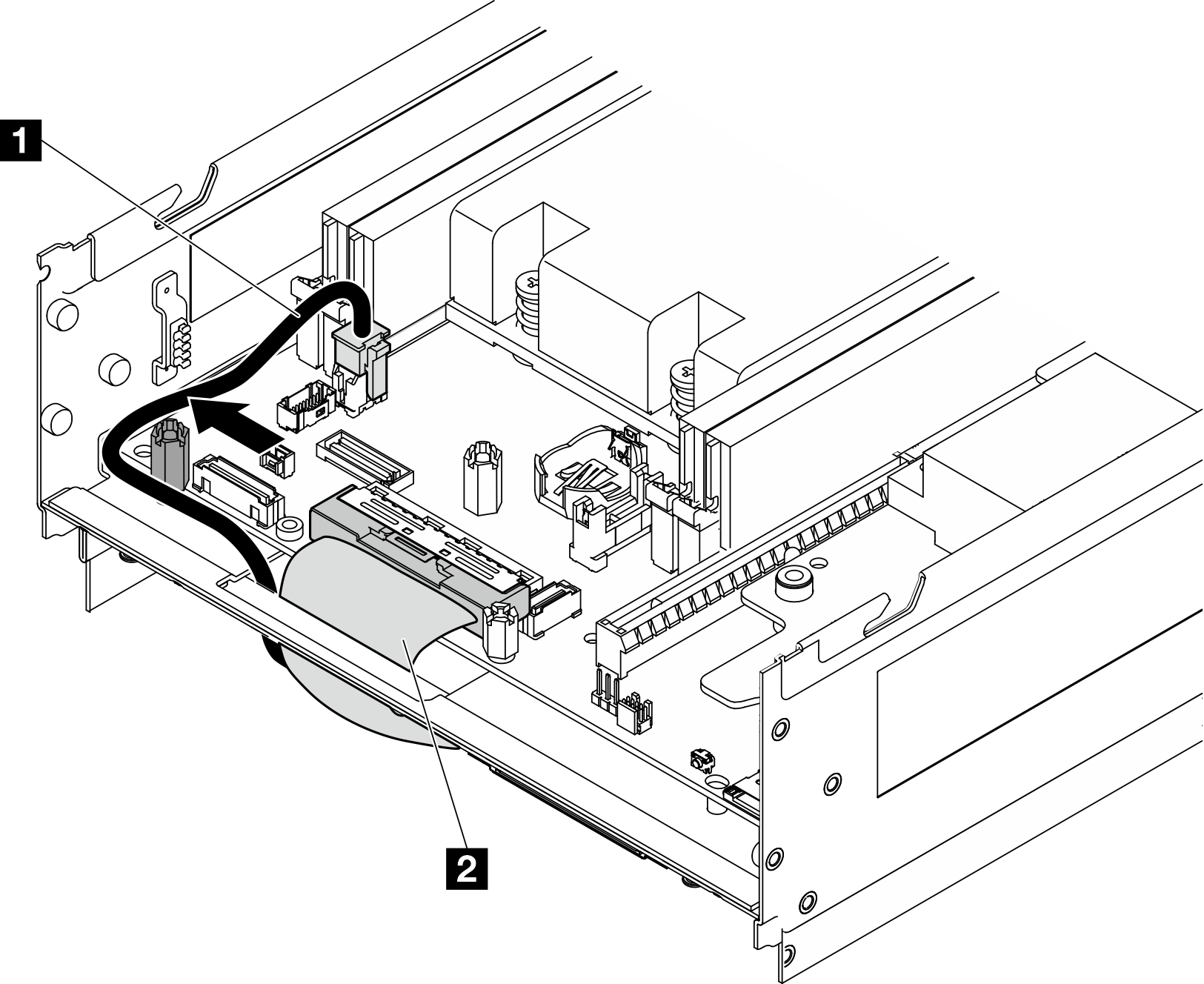
1 I/O-board power cable 2 I/O-board signal cable - Stick the Mylar film back to the node.Figure 2. I/O-board cable routing

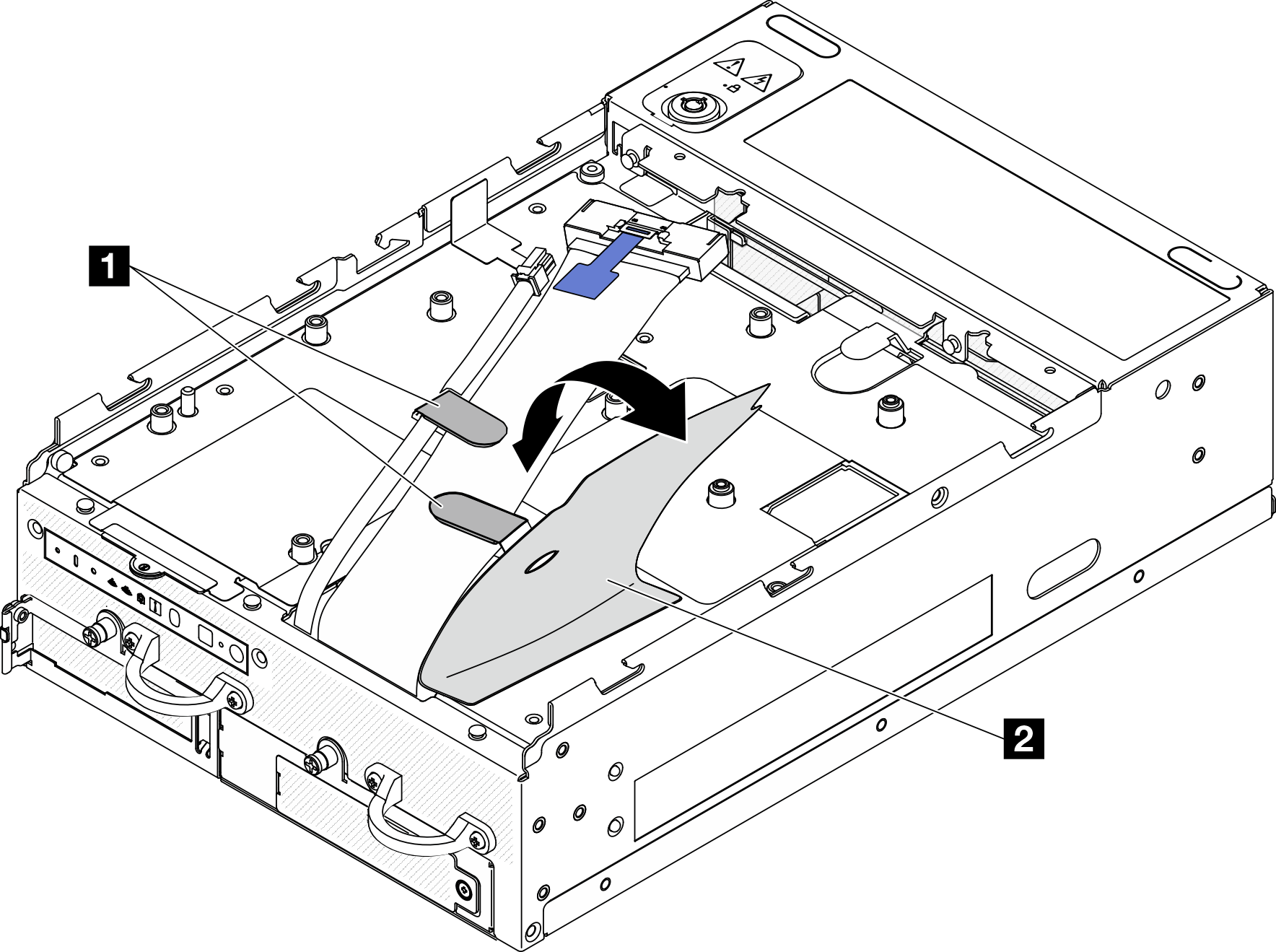
1 Cable clips 2 Mylar film
Install the I/O module board
Procedure
Note
Depending on the model, the I/O board might look slightly different from the illustrations in this section.
- Install the I/O module board.
- Align the I/O module board with the guide pins on the chassis.
- Lower the I/O module board down until it is firmly seated.
- Secure the I/O module board with six screws.
Figure 3. Installing the I/O module board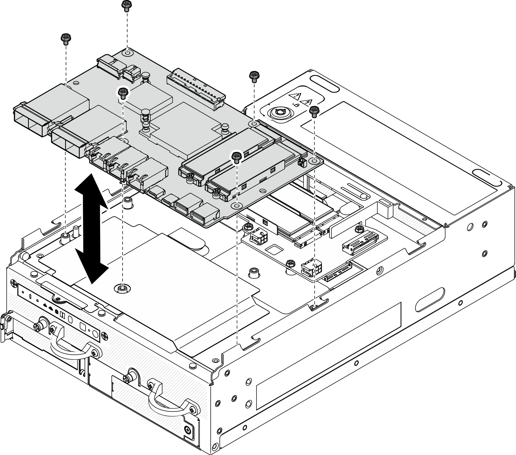
- Connect the cables to the I/O module board.
- Twist the I/O-board signal cable as shown; then, connect the signal cable and the power cable to the I/O module board.Figure 4. Connecting the I/O-board cables
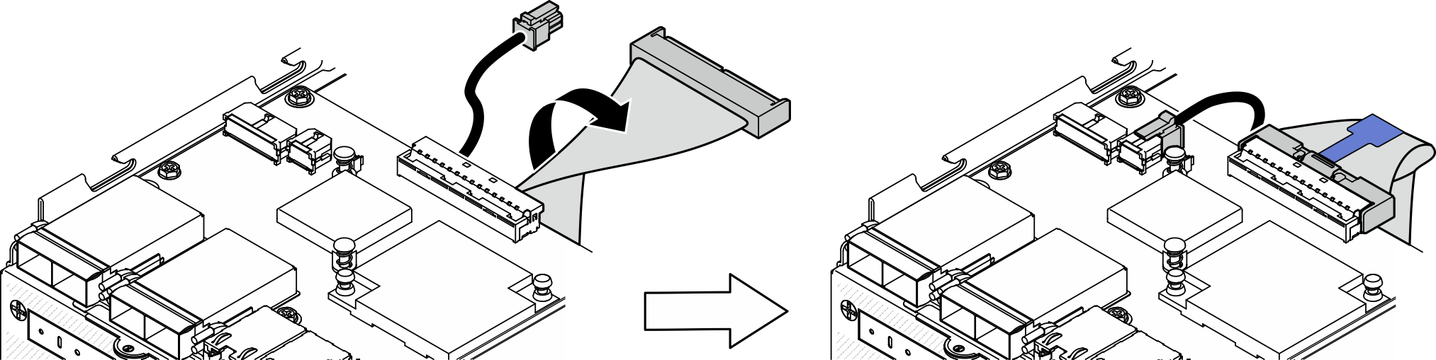
- Twist the I/O-board signal cable as shown; then, connect the signal cable and the power cable to the I/O module board.
Install an M.2 drive
If necessary, install an M.2 drive to the I/O module board.
- Locate the slot to install the M.2 drive.NoteThe slots are numbered to indicate the installation order. If only one M.2 drive is to be installed to the I/O module board, install the M.2 drive in Slot 1.
Slots on I/O module board 
1 Slot 2 / M.2 Bay 1 2 Slot 1 / M.2 Bay 0 - Install the M.2 drive.
 Hold the M.2 drive at an angle, and insert the drive into the M.2 slot.
 Lower the rear side of the M.2 drive down to the M.2 adapter.
 Secure the M.2 drive with one screw.
NoteIf necessary, repeat this procedure to the other M.2 drive to be installed.
Figure 5. Installing an M.2 drive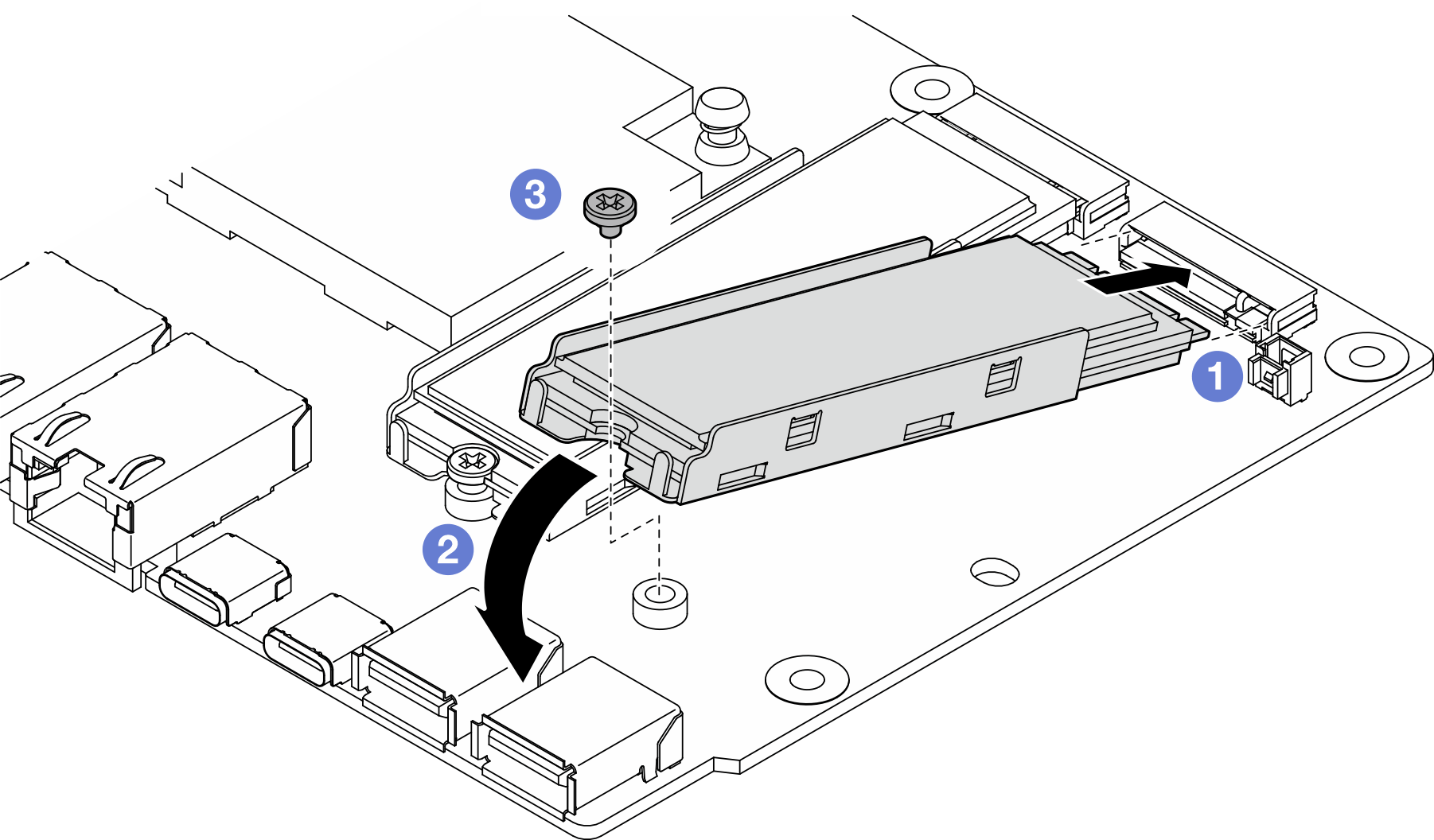
After this task is completed
Complete the parts replacement. See Complete the parts replacement.
Demo Video
Give documentation feedback