Remove the I/O module board and M.2 boot drives
Follow instructions in this section to remove the I/O module board and M.2 boot drives.
About this task
Read Installation Guidelines and Safety inspection checklist to ensure that you work safely.
Power off the server and peripheral devices and disconnect the power cords and all external cables. See Power off the server.
If the node is installed in an enclosure or mounted, remove the node from the enclosure or mount. See Configuration guide.
Procedure
Depending on the model, the I/O board might look slightly different from the illustrations in this section.
- Remove the bottom cover. See Remove the bottom cover.
Remove an M.2 drive
If necessary, remove an M.2 drive from the I/O module board.
Procedure
- Locate the M.2 drive to be removed.NoteThe slots are numbered to indicate the installation order. If only one M.2 drive is to be installed to the I/O module board, install the M.2 drive in Slot 1.
Slots on I/O module board 
1 Slot 2 / M.2 Bay 1 2 Slot 1 / M.2 Bay 0 - Remove the M.2 drive.
 Loosen the screw that secures the M.2 drive.
 Pivot the rear side of the M.2 drive away from the M.2 adapter.
 Remove the M.2 drive from the slot.
NoteIf necessary, repeat this procedure to the other M.2 drive to be removed.
Figure 1. Removing an M.2 drive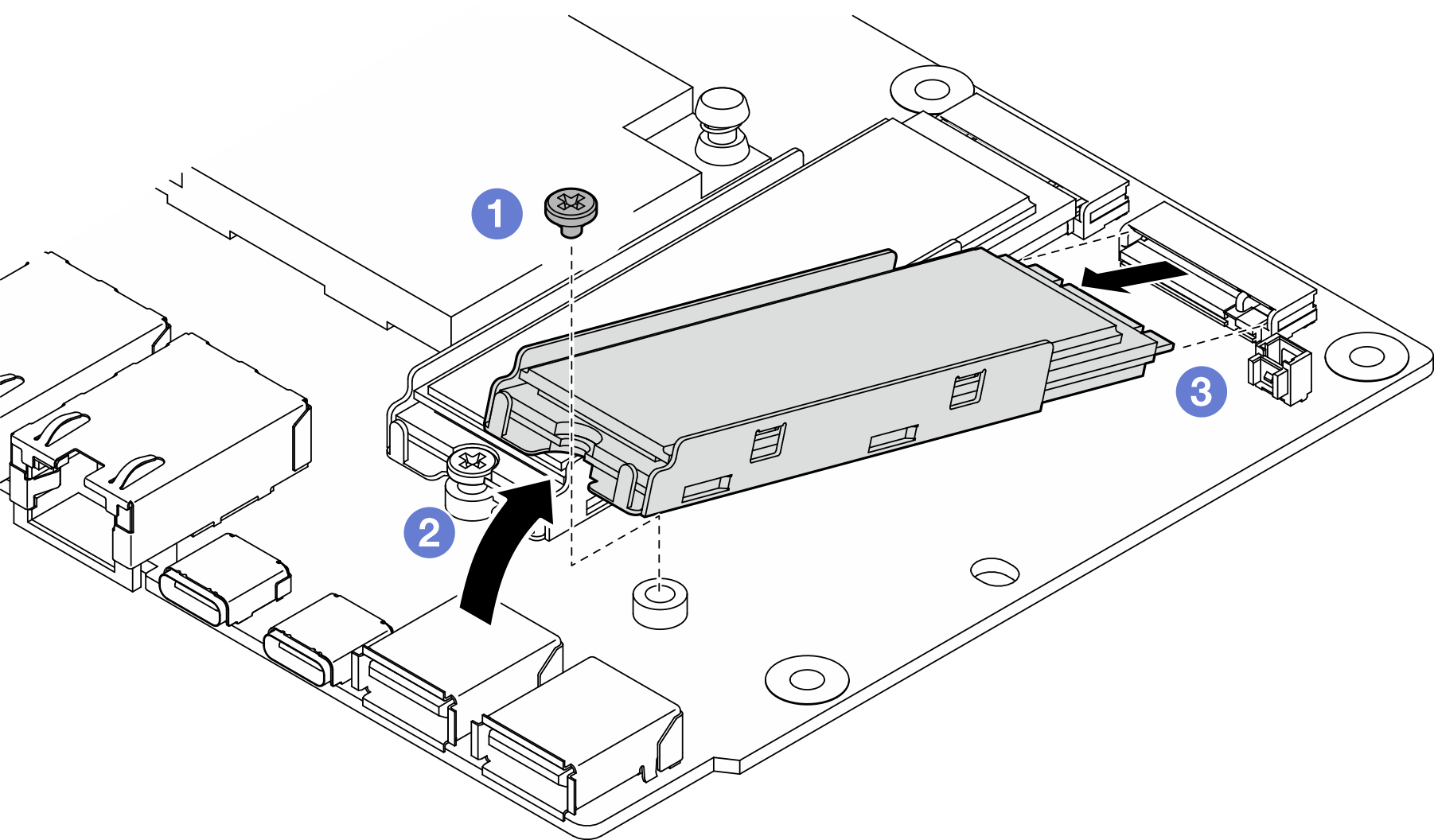
Remove the I/O module board
Procedure
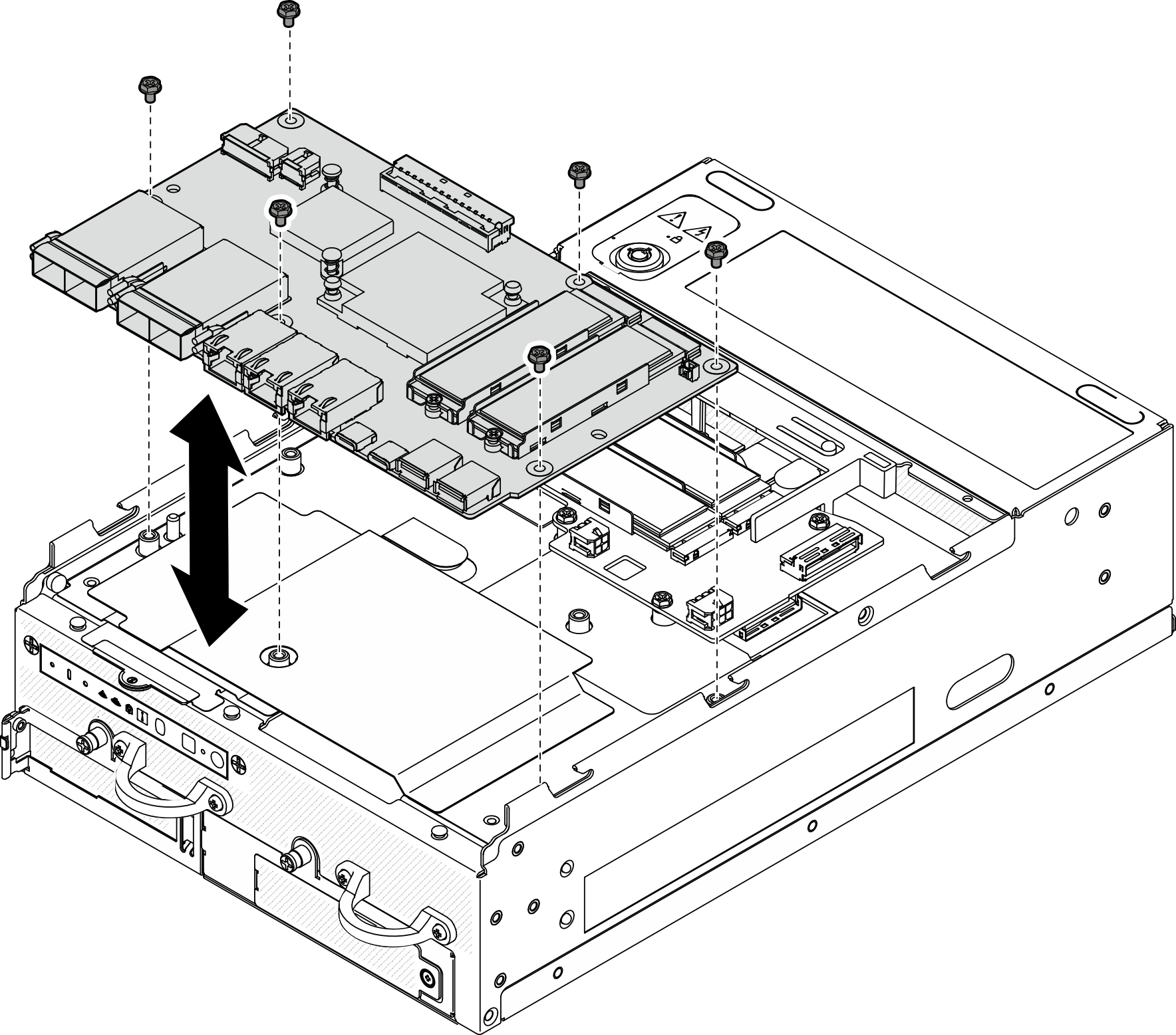
- Lift the I/O module board to remove it.Figure 2. Removing the I/O module board
Remove the I/O-board power and signal cable
Procedure
- Stick the Mylar film back to the node.Figure 3. I/O-board cable routing

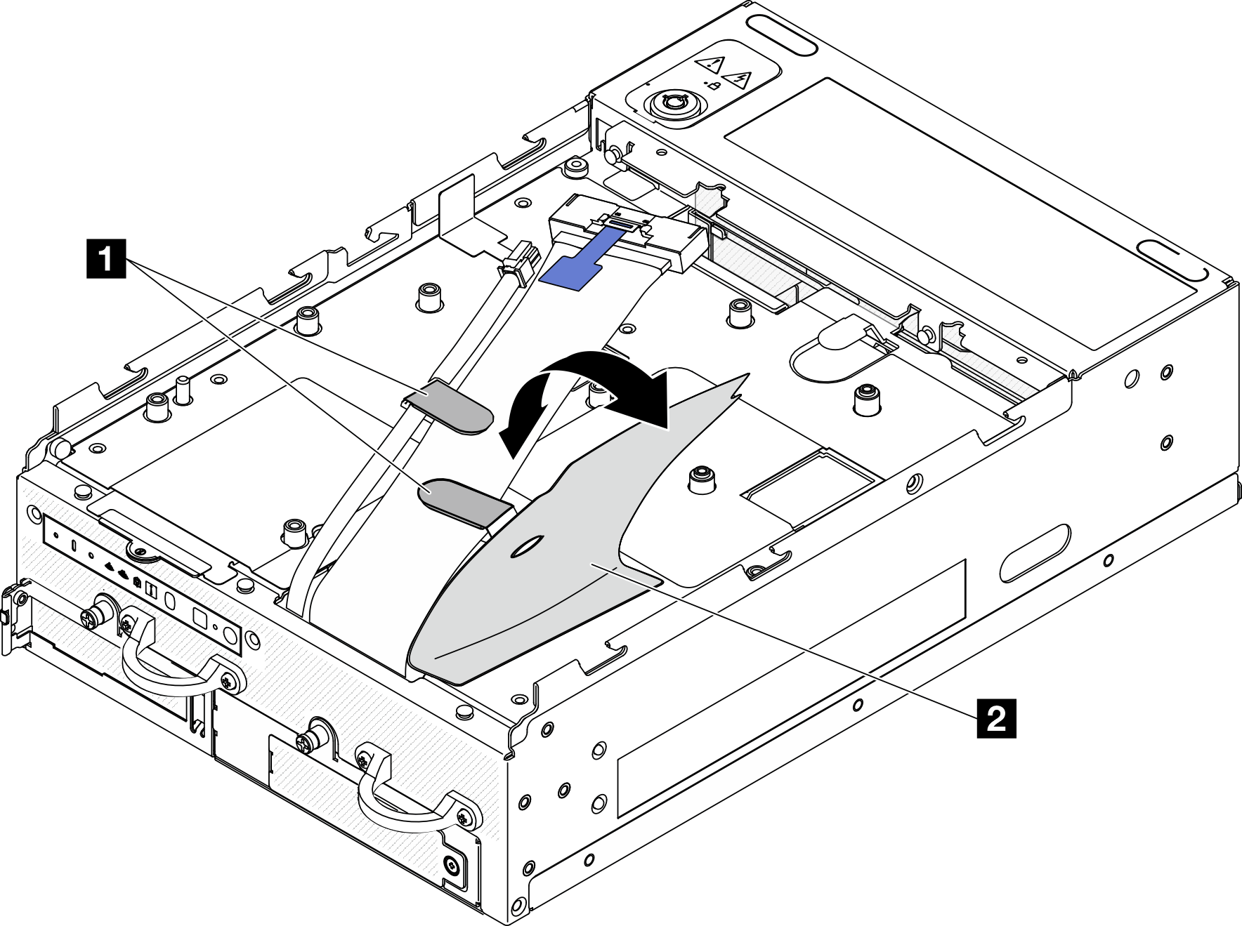
1 Cable clips 2 Mylar film - Disconnect the I/O-board power cable and signal cable from the system board; then, remove the cables from the chassis.Figure 4. I/O-board cable routing
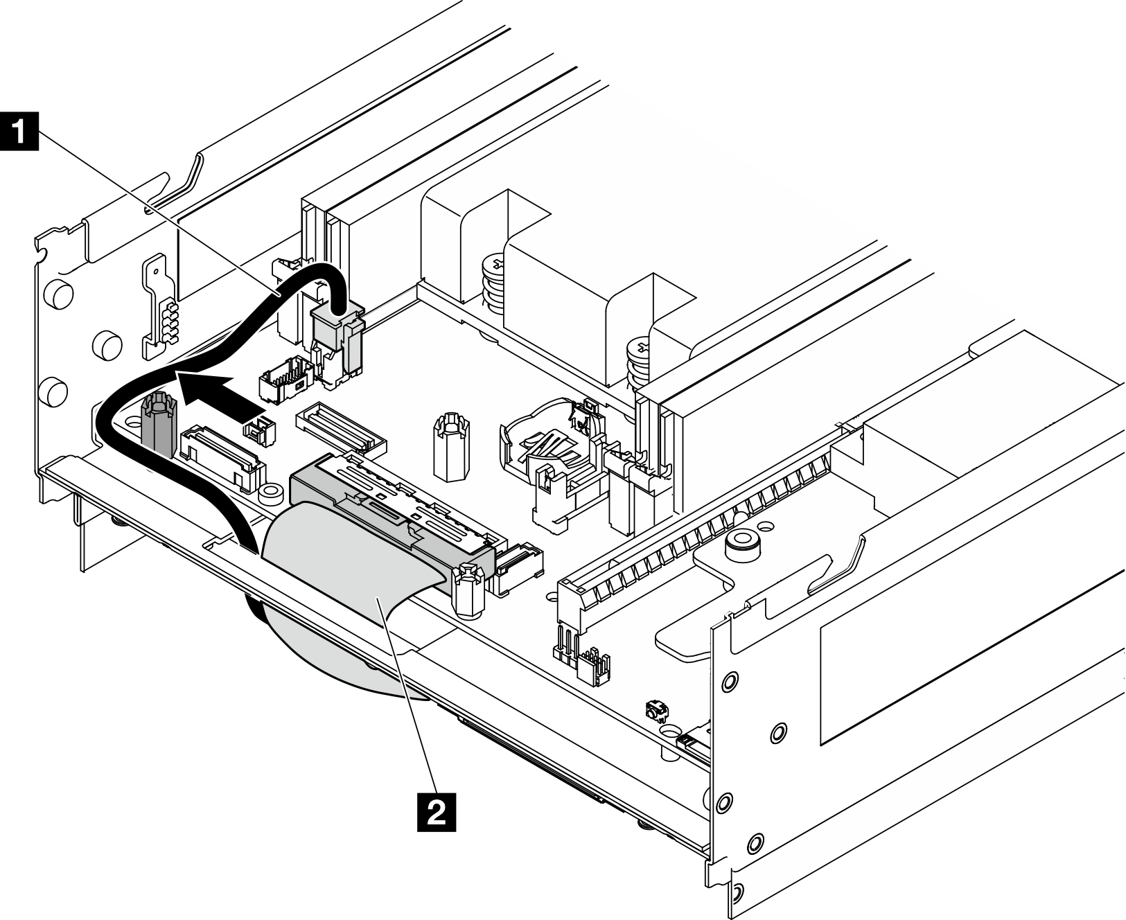
1 I/O-board power cable 2 I/O-board signal cable
After this task is completed
Install a replacement unit. See Install the I/O module board and M.2 boot drives.
If you are instructed to return the component or optional device, follow all packaging instructions, and use any packaging materials for shipping that are supplied to you.
Demo Video