CFF RAID/HBA adapter
Use the section to understand the power cable and signal input cable routing for CFF RAID/HBA adapters.
Cable routing for CFF RAID adapters
For the locations of connectors on the processor board, refer to System-board-assembly connectors.
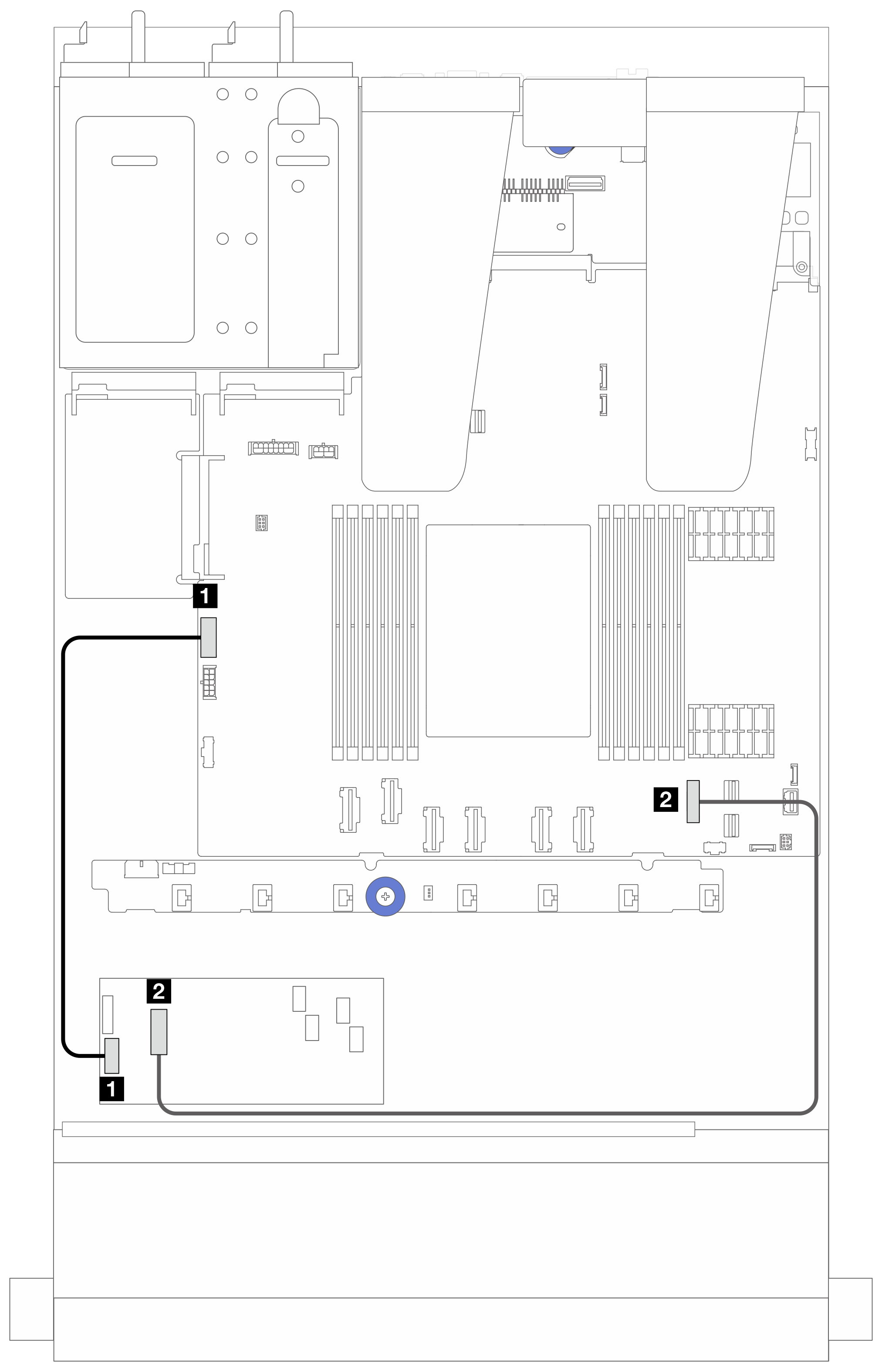
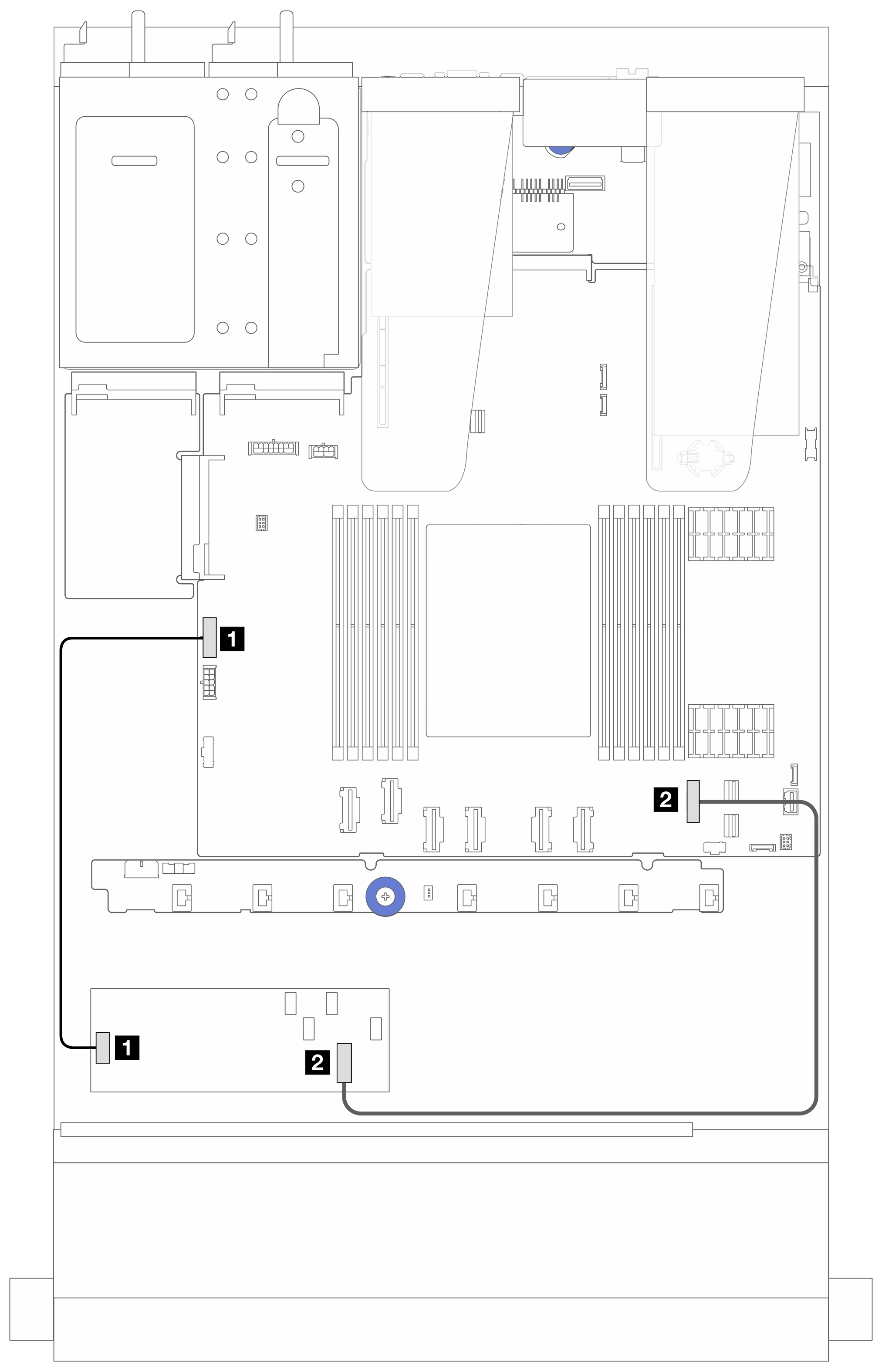
The figures below present the power and input cable routing of CFF RAID/HBA adapters.
Figure 1. Gen 3 CFF RAID/HBA adapter power and input cabling


| From | To |
|---|---|
| 1 CFF power on the CFF RAID/HBA adapter | 1 Internal RAID power connector |
| 2 CFF input on the CFF RAID/HBA adapter | 2 PCIe connector 7 on the processor board |
Figure 2. Gen 4 CFF RAID adapter power and input cabling


| From | To |
|---|---|
| 1 CFF power on the CFF RAID/HBA adapter | 1 Internal RAID power connector |
| 2 CFF input on the CFF RAID/HBA adapter | 2 PCIe connector 7 on the processor board |
Give documentation feedback