OCP interposer card
Use the section to understand the cable routing between two OCP interposer cards and the system board assembly.
Figure 1. Cable routing for the OCP interposer cards
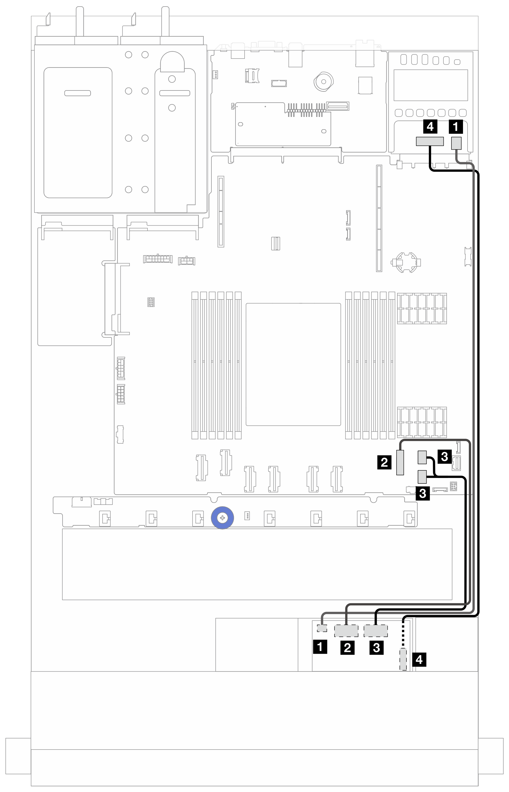
| From | To |
| 1 Front OCP interposer power | 1 Rear OCP interposer power |
| 2 Front OCP interposer signal (MCIO 2) | 2 PCIe connector 7 on the system board assembly |
| 3 Front OCP interposer signal (MCIO 1) | 3 PCIe connectors 8 and 9 on the system board assembly |
| 4 Front OCP interposer power sideband (SWIFT) | 4 Rear OCP interposer power sideband (SWIFT) |
Give documentation feedback