4 x 2.5'' NVMe backplane (Gen 4)
Use this section to understand the NVMe backplane (Gen 4) cable routing for server model with four 2.5'' front drives.
To connect power cables for a backplane for standard 2.5'' or 3.5'' drives, refer to Backplane power cable routing.
To connect cables for intrusion switch, refer to Intrusion switch.
Cable routing for onboard configuration with one processor
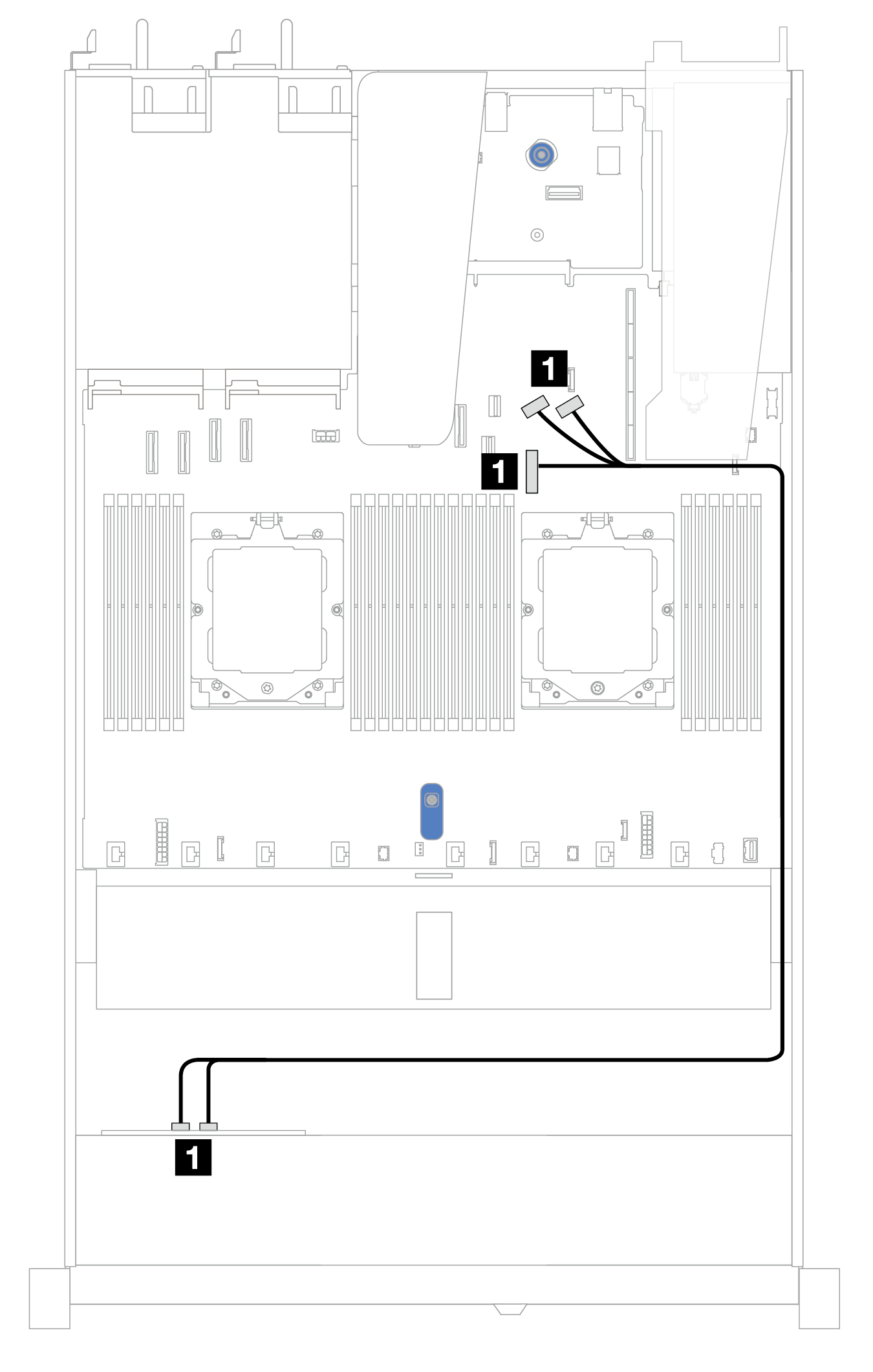
Figure 1. Mapping between 4 x 2.5'' front NVMe drive backplane and system board for onboard configuration with one processor (Gen 4)
Note
This cable routing is for the configuration without M.2 SATA/NVMe drive PCIe 4.0 backplane and front I/O module.
| Backplane | From | To |
|---|---|---|
| Front BP (NVMe) | 1 NVMe 0–1, NVMe 2–3 | 1 PCIe connectors 7, 8, and 9 |
Give documentation feedback