M.2 drive backplane
This section provides cable routing information for the M.2 drives. Your server supports M.2 SATA/NVMe drive backplanes.
Locations of M.2 drive assemblies
The locations of M.2 drive assemblies vary in different configuration. The server has two locations for M.2 drive assemblies.
Figure 1. An M.2 drive assembly in the 2.5/3.5-inch drive chassis 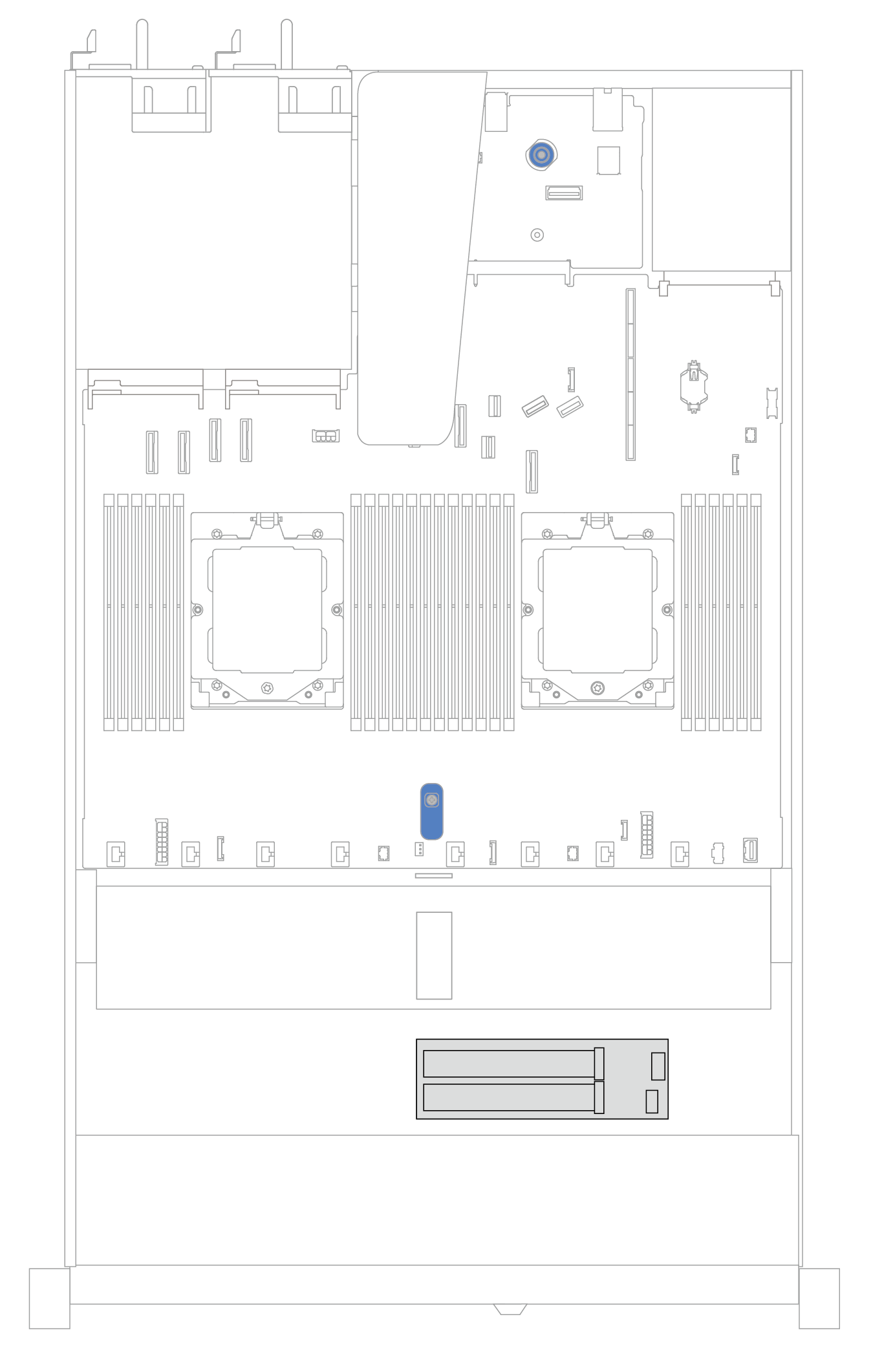 | Figure 2. An M.2 drive assembly in the 16-EDSFF drive chassis 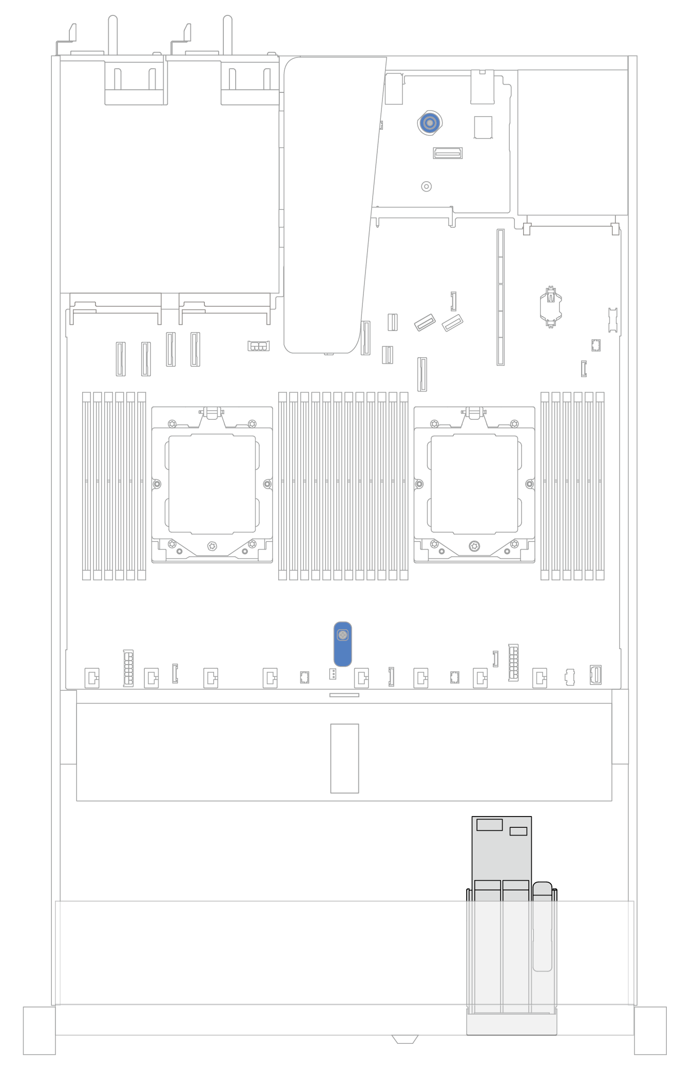 |
Cable routing of the M.2 drive backplanes
For the locations of M.2 connectors on the backplanes and the processor board, see M.2 backplane and M.2 drive replacement and System-board-assembly connectors for details.
The following illustrations and tables list the M.2 drive backplanes supported:
M.2 x4 non-RAID SATA/NVMe 2-bay backplanes
Figure 3. Cable routing for M.2 x4 non-RAID SATA/NVMe 2-bay backplanes
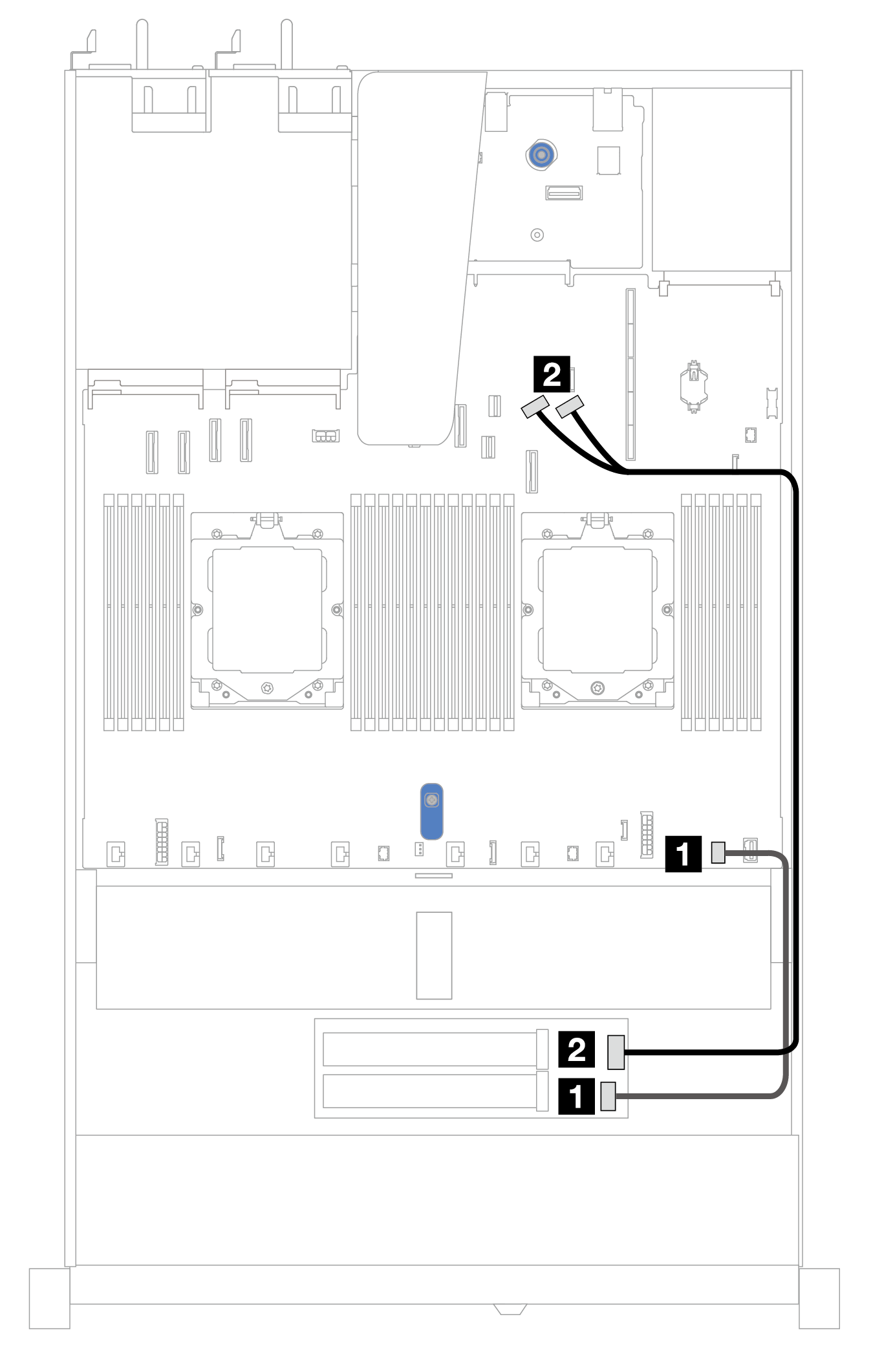
| From | To |
|---|---|
| 1 M.2 power connector | 1 M.2 power connector on the processor board |
| 2 M.2 signal connector | 2 PCIe connectors 8 and 9 on the processor board |
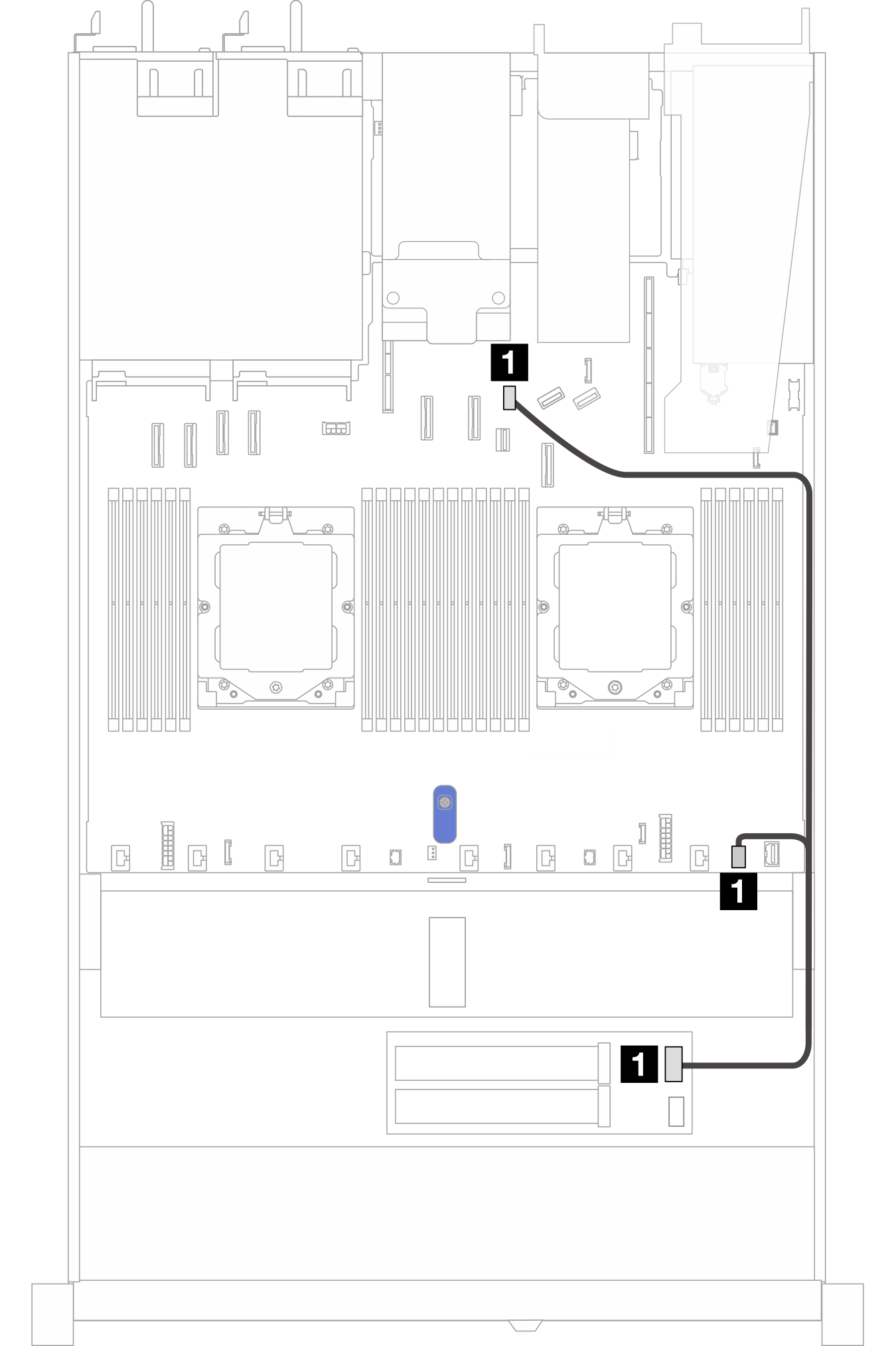
M.2 x1 RAID NVMe 2-bay backplanes
Figure 4. M.2 x1 RAID NVMe 2-bay configuration 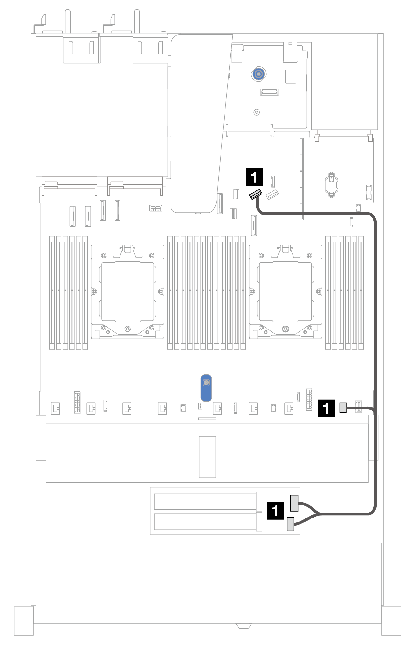 | Figure 5. M.2 x1 RAID NVMe 2-bay configuration 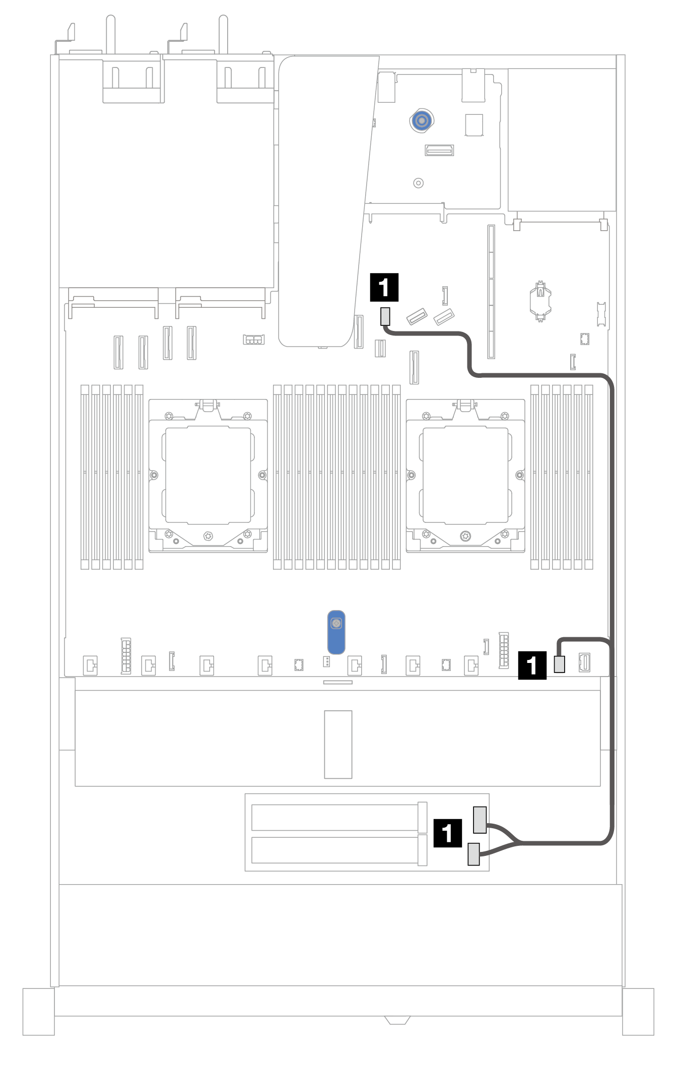 | ||
| From | To | From | To |
| 1 M.2 signal connector and power connector | 1 PCIe connector 8 and M.2 power connector on the processor board | 1 M.2 signal connector and power connector | 1 M.2 signal connector and M.2 power connector on the processor board |
M.2 RAID SATA/NVME 2-bay backplanes
Figure 6. Cable routing for M.2 RAID SATA/NVME 2-bay backplanes
| From | To |
|---|---|
| 1 M.2 backplane | 1 M.2 signal connector and M.2 power connector on the processor board |
M.2 backplane to SFF RAID adapters
Note
This cable routing is only applicable to the following backplanes:
M.2 x4 non-RAID SATA/NVMe 2-bay backplanes
M.2 x1 RAID NVMe 2-bay backplanes
Figure 7. Cable routing for M.2 backplane to an 8i SFF RAID adapter (Gen 3 or Gen 4)
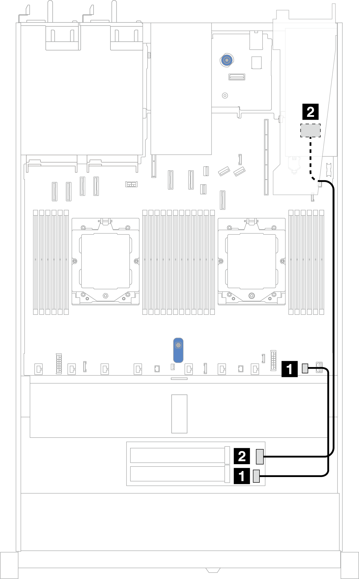
| From | To |
|---|---|
| 1 M.2 power connector | 1 M.2 power connector on the processor board |
| 2 M.2 signal connector | 2 SFF RAID connector
|
Give documentation feedback