Front I/O module
Use the section to understand the cable routing for front I/O module.
Note
The illustration shows the cabling scenario for server models with 2.5'' and 3.5'' front drive bays. Location of each connector on the front of the server varies by models. For detailed location of front I/O components for different models, see Front view.
Figure 1. Cable routing for a front I/O module on 2.5'' chassis 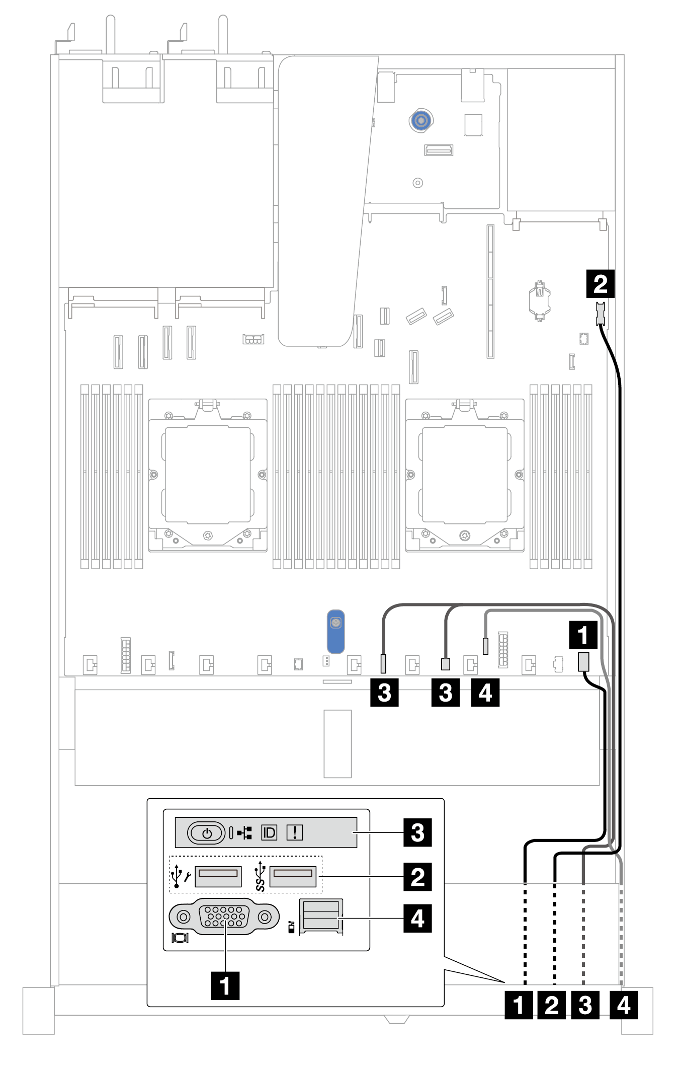 | Figure 2. Cable routing for a front I/O module on 3.5'' chassis 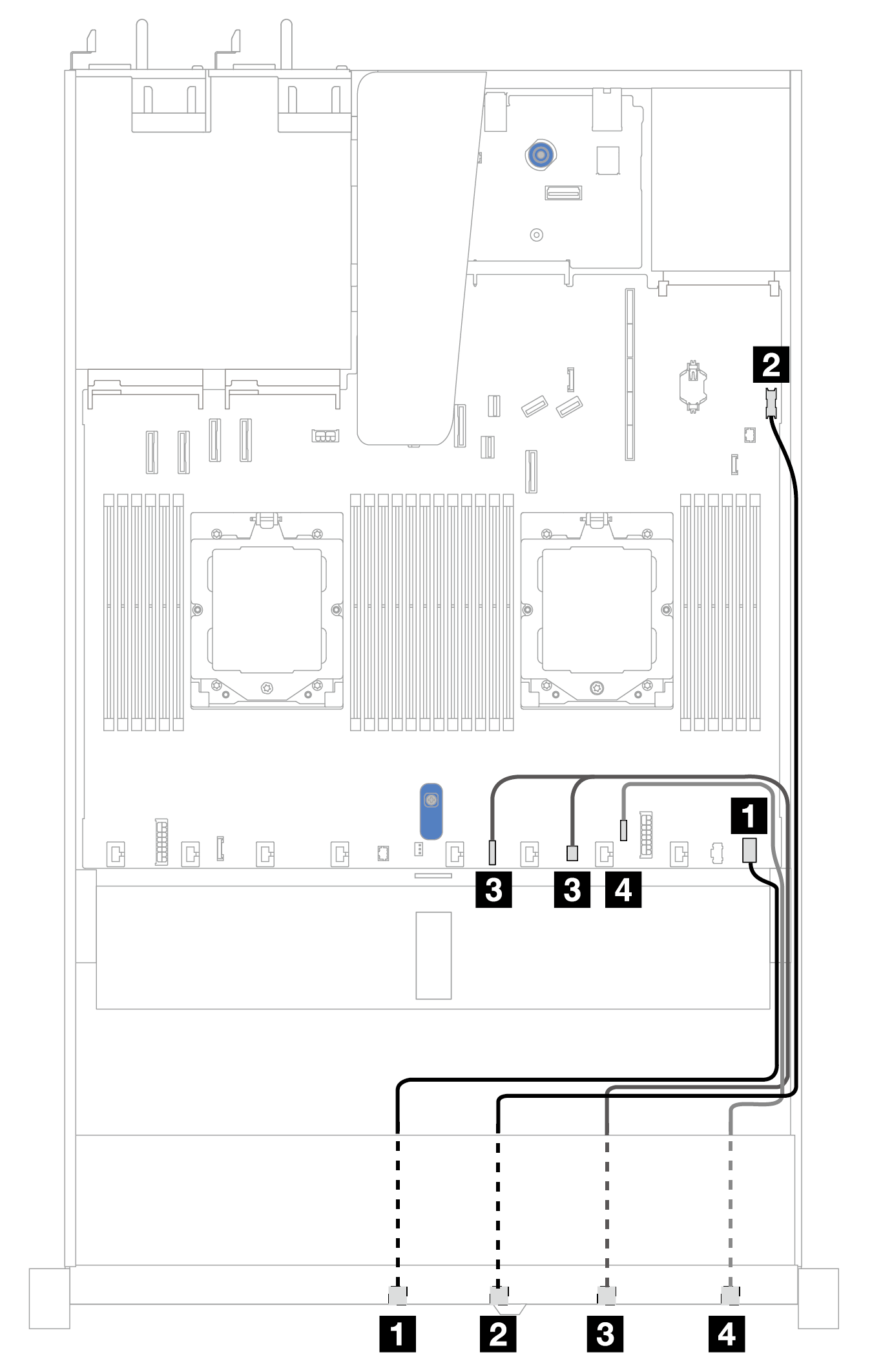 | ||
| From | To | From | To |
| 1 VGA connector | 1 Front VGA connector on the processor board | 1 VGA connector | 1 Front VGA connector on the processor board |
| 2 Front USB connector | 2 Front USB connector on the processor board | 2 Front USB connector | 2 Front USB connector on the processor board |
| 3 Front operator panel | 3 FIO_Y cable connector and FIO connector on the processor board | 3 Front operator panel | 3 FIO_Y cable connector and FIO connector on the processor board |
| 4 External diagnostics connectorNote | 4 External diagnostics connector on the processor board | 4 External diagnostics connector | 4 External diagnostics connector on the processor board |
Note The external diagnostics connector is not available on certain front I/O modules of 10 x 2.5'' server models. | |||
Give documentation feedback