CFF 16i RAID/HBA adapter + 8i RAID adapter (Tri-mode)
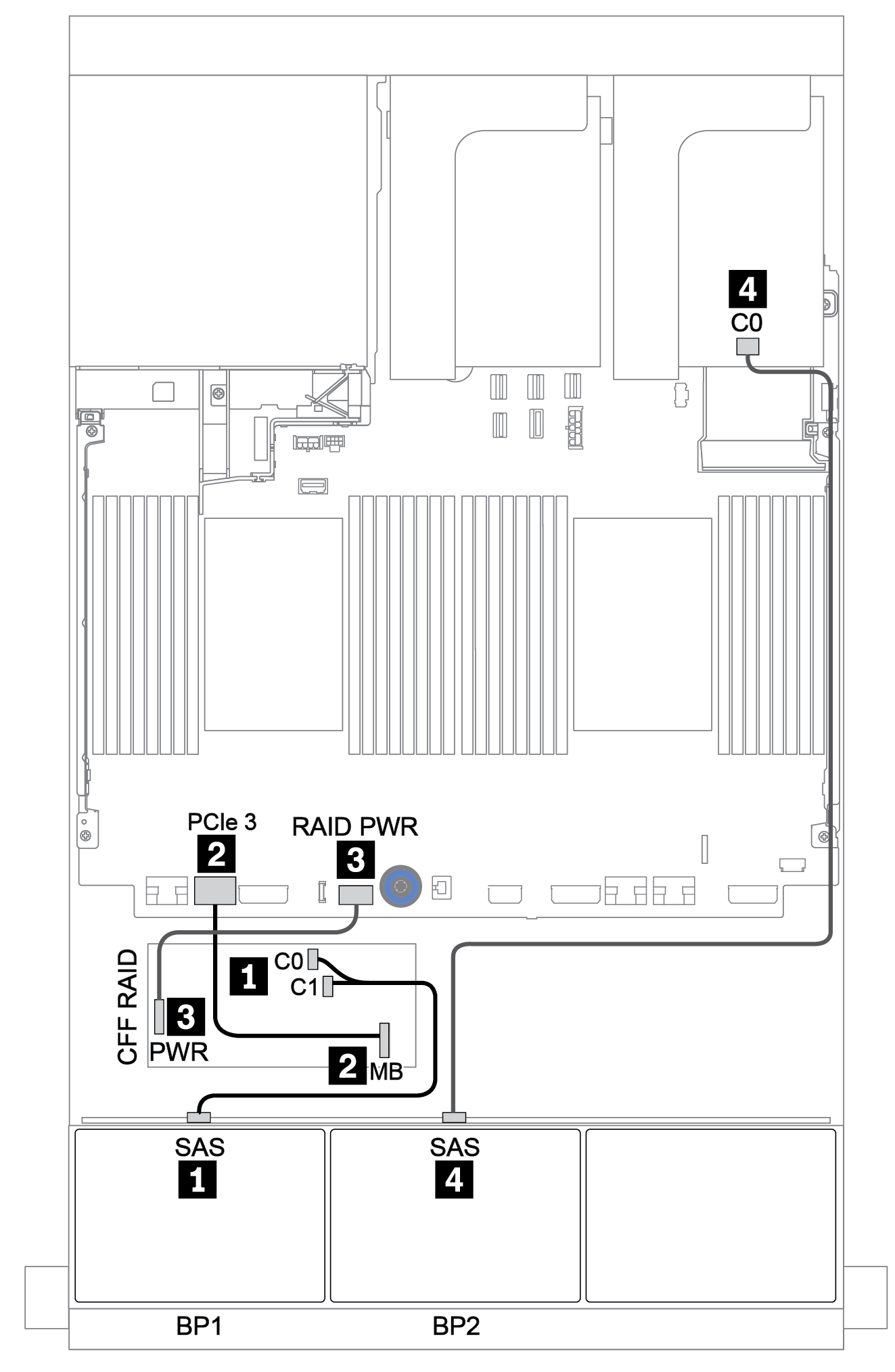
The following shows the cable connections for the 8 x 2.5-inch SAS/SATA + 8 x 2.5-inch AnyBay configuration with one CFF 16i RAID/HBA adapter and one Tri-mode 8i RAID adapter for U.3 drives.
| From | To |
|---|---|
Backplane 1: SAS | CFF 16i RAID/HBA adapter: C0, C1 |
CFF 16i RAID/HBA adapter: MB (CFF input) |
|
CFF 16i RAID/HBA adapter: PWR | Onboard: RAID PWR |
Backplane 2: SAS | Tri-mode 8i RAID adapter on PCIe slot 2: C0 |
Connections between connectors: 1 ↔ 1, 2 ↔ 2, 3 ↔ 3, ... n ↔ n
The CFF adapter in the following illustration might look slightly different from your CFF adapter, but the cable connections are the same.
The following illustration shows the cable routing when two processors are installed. When only one processor is installed, the only different is cable 3 which should be connected to PCIe 1 or PCIe 2 on the system board.